
More project photos (2)
The problem
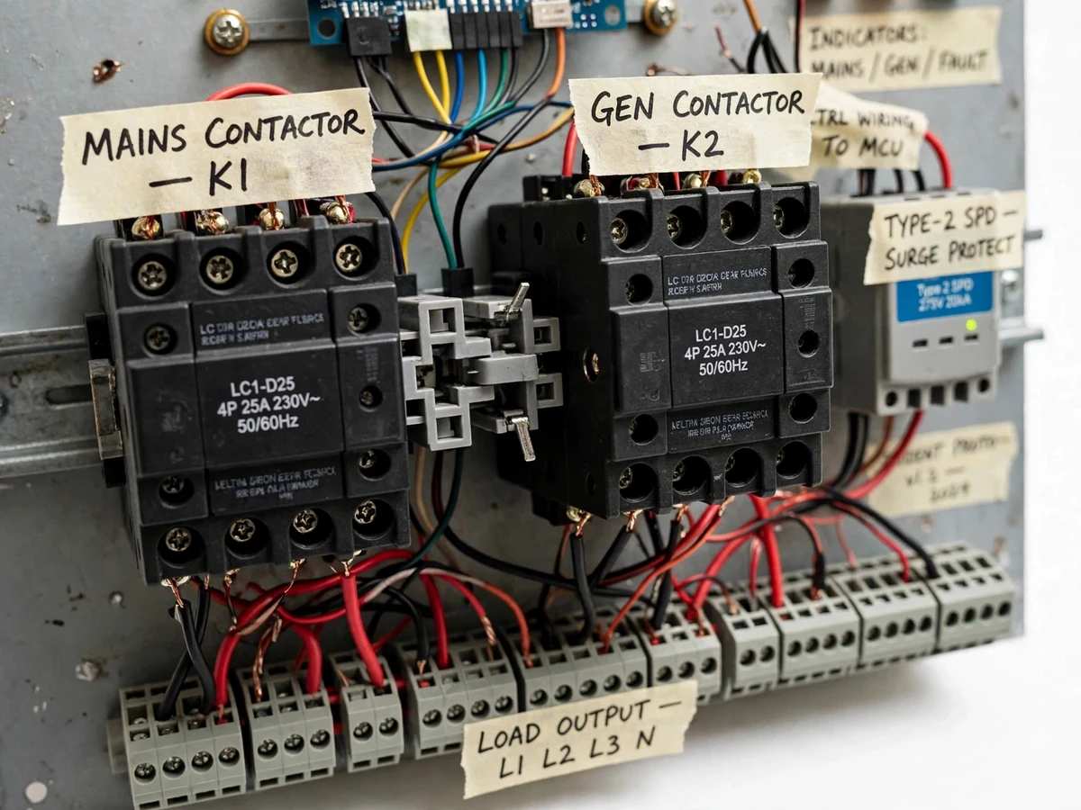
Homes, small workshops and rural installations with a standby generator usually depend on a manual changeover switch or a basic voltage-relay automatic transfer panel. Both leave two gaps that students rarely confront in the lab. First, when the mains sags into a brownout instead of failing cleanly, a plain relay changeover chatters or transfers the load onto a dying supply, and repeated restarts stress whatever is connected. Second, every restoration transient and lightning-induced surge on the incoming line passes straight through to the load and the switching gear itself. Manual changeover adds a third risk: it depends on someone being present, and a mistimed operation can parallel both sources. This project builds a panel that closes those specific gaps — a microcontroller supervises the mains voltage continuously and permits transfer only when the supply is genuinely healthy, an undervoltage lockout holds the system against brownouts, a Type-2 surge protection device guards the mains incomer, and break-before-make sequencing runs through two interlocked contactors so both sources can never connect together.
Utility incomer feeding the panel through a Type-2 surge protection device.
Follow the working sequence
How it works
- Potential transformers and voltage sensing relays step the mains and generator voltages down to a safe level for the controller's ADC inputs.
- The microcontroller samples the mains voltage continuously and compares it against the configured undervoltage threshold (approximately 180 V, adjustable in firmware).
- On a genuine mains failure — voltage below threshold for the confirmation time — the controller drops the mains contactor K1, waits the configured generator warm-up delay (5–10 s), then closes the generator contactor K2. The sequence is break-before-make: both sources are never connected together.
- A Type-2 SPD on the mains incomer clamps any transient overvoltage arriving from the supply side.
- When the mains returns and stays above the threshold through the stabilization delay, the controller drops K2 and re-closes K1, returning the load to mains supply.
- If the mains sits in a brownout band (weak but not failed), the undervoltage lockout holds the panel in its current state instead of chattering; any detected fault latches a manual-reset lockout with the FAULT lamp and buzzer on.
Tech stack:
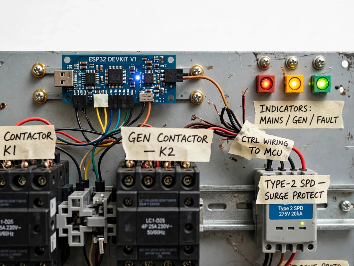
- ESP32 development board (controller)
- Arduino IDE · C/C++ firmware
- 25 A 4-pole contactors · mechanical interlock
- Type-2 surge protection device (275 V · 20 kA)
- Voltage sensing relays · potential transformers
- Undervoltage lockout logic
- MCBs · manual bypass switches
- Indicator lamps · buzzer · terminal blocks
| Parameter | Value |
|---|---|
| Mains supply | 230 V AC nominal, single-phase to three-phase (design) |
| Undervoltage lockout threshold | Approximately 180 V, adjustable in firmware (design target) |
| Contactors | 2 × 25 A 4-pole, mechanically + electrically interlocked (approximate rating) |
| Generator warm-up delay | 5–10 s, configurable (design target) |
| Re-transfer stabilization delay | Approximately 30 s, configurable (design target) |
| Transfer type | Break-before-make, single source at a time (design) |
| Surge protection | Type-2 SPD, 275 V, 20 kA nominal discharge (datasheet values) |
| Demo load | Scaled lamp load, approximately 200–500 W per phase (demonstration only) |
| Controller supply | 230 V AC to 5 V DC via control transformer + regulator (design) |
| Enclosure | Metal panel board, DIN-rail mounted components (design) |
Project features
- [Microcontroller-based voltage supervision] An ESP32 development board continuously samples the stepped-down mains and generator voltages and decides every transfer on live data, instead of relying on a fixed-threshold voltage relay.
- [Undervoltage lockout] When the mains sits in a brownout band — weak but not failed — the firmware blocks generator start and holds the current state, so the panel never chatters between sources or transfers onto a dying supply.
- [Adjustable UV threshold] The lockout threshold is a firmware set point (design target approximately 180 V on a 230 V nominal), adjustable to suit the local supply, with a buyer-run calibration procedure using their own multimeter.
- [Type-2 surge protection on the mains incomer] A DIN-mounted Type-2 SPD clamps transient overvoltages before they reach the contactors and the load; its status window shows SPD health at a glance.
- [Interlocked 25 A 4-pole contactors, break-before-make] A mechanical interlock bar between the two contactors plus electrical interlocking in the wiring means the outgoing source is always confirmed dropped before the other closes.
- [Configurable warm-up and stabilization delays] The generator gets a configurable warm-up delay (5–10 s design target) before load transfer, and re-transfer to mains happens only after the mains stays healthy through a stabilization delay.
- [Fault lockout with manual reset] On detected faults such as a failed transfer or sustained undervoltage, the controller latches a lockout state that requires manual reset — no automatic retry loops.
- [Manual bypass and status indication] Manual bypass switches allow maintenance isolation, while MAINS / GEN / FAULT indicator lamps and a buzzer make the panel state obvious during demonstrations.
What is included
- Working changeover control panel prototype (2 × 25 A interlocked contactors, ESP32 controller board, Type-2 SPD, MCBs, manual bypass switches, indicator lamps, terminal blocks)
- Controller firmware source code (C/C++, commented) with configurable thresholds and delays
- Wiring diagram and terminal schedule
- Component list with approximate ratings
- Threshold-calibration and demonstration procedure (buyer-run, with their own multimeter)
- Project report PDF (background, protection theory, sequencing logic, calibration procedure)
- PPT presentation for final review
- Viva Q&A preparation document (ATS concepts, undervoltage protection, SPD coordination, interlocking)
Limitations & prerequisites
- Prototype panel built for demonstration and academic study — it is not a certified, utility-grade automatic transfer switch and must not be presented or sold as one.
- Contactor and MCB ratings (25 A class) are approximate and chosen for the demo load range; protection sizing for a real installation is a separate engineering task for the buyer.
- Switching and transfer timings are design targets verified functionally on scaled loads, not lab-measured performance figures.
- Generator-side wiring and any connection to a real generator set must be carried out by a qualified electrician; the shipped demo uses scaled lamp loads, not a live generator.
- The Type-2 SPD protects the panel incomer only; whole-installation surge coordination needs a proper earthing system, which the demo rig does not replace.
- Voltage sensing is functional-grade, not metering-grade — thresholds are adjustable set points to be verified with the buyer's own instruments during calibration.
Frequently Asked Questions
How is this different from a basic automatic changeover switch?
A basic changeover switches on fixed voltage-relay thresholds and will chatter or transfer onto a weak, dying mains during brownouts. This build adds a microcontroller that supervises the mains continuously with an undervoltage lockout — transfer happens only on a genuinely healthy supply — plus a Type-2 SPD on the incomer that the plain relay version does not have.
What does the undervoltage lockout actually do?
It continuously compares the mains voltage against an adjustable threshold (design target approximately 180 V). If the supply is weak but not failed, it blocks generator start and holds the panel in its current state instead of transferring back and forth. The threshold is a firmware set point the student calibrates with their own multimeter.
Can this panel be connected to a real home generator?
The shipped prototype is demonstrated on scaled lamp loads. Any connection to a real generator set or household wiring must be done by a qualified electrician after proper protection sizing — that site work is outside the project scope.
Can the delays and thresholds be changed?
Yes. The warm-up delay (5–10 s), re-transfer stabilization delay and UV threshold are firmware constants with a documented adjustment and calibration procedure, so the student can demonstrate the effect of different settings in the viva.
Is this project suitable for a final-year project?
Yes — for Electrical and Electronics & Telecommunication programs. It demonstrates protection coordination, contactor interlocking, sequencing logic, surge protection and microcontroller-based supervision in one build. Suitable for B.E./B.Tech final-year projects in Electrical and Electronics & Telecommunication Engineering.
Components & software requirements
- ESP32 development board (controller)
- Arduino IDE · C/C++ firmware
- 25 A 4-pole contactors · mechanical interlock
- Type-2 surge protection device (275 V · 20 kA)
- Voltage sensing relays · potential transformers
- Undervoltage lockout logic
- MCBs · manual bypass switches
- Indicator lamps · buzzer · terminal blocks
Delivery information
Built-to-order project. Delivery timeline is shared after order confirmation based on current queue.
Support terms
Complete documentation, setup guide, and viva preparation included. Support for setup and explanation provided.
Download free synopsis (PDF)
Enter your name and email — the synopsis PDF downloads immediately. We may send occasional project updates; no spam, unsubscribe anytime.