
More project photos (2)
The problem
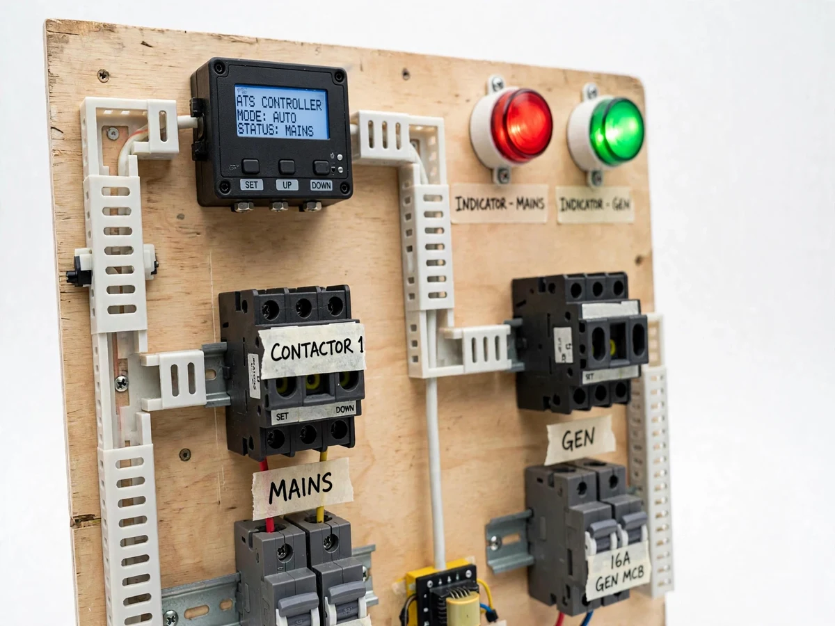
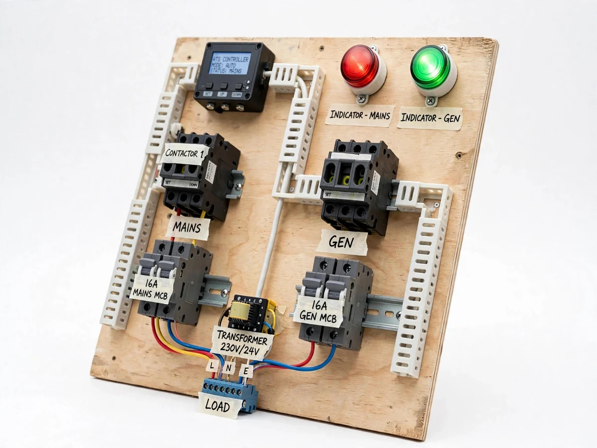
Hospitals, data centers and apartment buildings depend on automatic transfer switches to move critical loads from mains to a standby generator when the grid fails — but students study ATS only as a block diagram, never seeing the sensing, timing and interlocking that make it safe. A wrong changeover welds contacts, backfeeds the generator into the grid, or drops the load twice. This trainer makes the sequence physical: a mains-sensing relay watches the supply, a timer module implements the start delay and transfer delay, and two interlocked contactors perform the actual changeover to a simulated generator source, with indicator lamps and a transfer-time measurement point at every stage. Every timing in the sequence is configurable and measurable, so the viva can be answered with the panel in front of the student.
How it works
- With mains healthy, the sensing relay holds the mains contactor closed and the load runs on mains; the GENERATOR contactor is locked out by the interlock.
- When mains voltage drops below the sensing threshold, the start delay timer begins — this rides through momentary dips without transferring.
- After the start delay, the simulated generator source is "started" (energized) and the transfer delay runs to let it stabilize.
- The mains contactor drops out, the interlock releases, and the generator contactor pulls in — the load is now on the generator supply, with the changeover interval measurable at the test points.
- When mains returns and stays healthy through the retransfer delay, the sequence reverses: load back to mains, generator source shut down.
- Throughout, the electrical + mechanical interlock guarantees the two sources can never be paralleled, and the emergency stop drops both contactors.
Tech stack:
- 2 × power contactors with mechanical interlock accessory
- Voltage-sensing / phase-monitoring relay
- ON-delay timer modules (start, transfer, retransfer delays)
- MCBs for mains input, generator input and load output
- Panel indicator lamps, emergency stop pushbutton
- Steel enclosure trainer panel with labeled terminals
- Stopwatch / oscilloscope for the buyer-run transfer-time test
| Parameter | Value |
|---|---|
| Supply | 230 V AC single-phase mains input + simulated generator input |
| Contactors | 2 × 25 A (or per load design), mechanically + electrically interlocked |
| Transfer time | Design target < 1 s changeover interval (measured by the buyer with the documented procedure, not claimed as measured) |
| Sensing | Adjustable undervoltage dropout threshold on the sensing relay |
| Timers | Start / transfer / retransfer delays, each adjustable over the timer's range |
| Protection | Input MCBs on both sources, emergency stop, shrouded terminals |
| Panel | Labeled steel enclosure with status lamps and test points |
Project features
- [Mains-failure sensing] Voltage-sensing relay monitors the mains input; dropout below the threshold starts the transfer sequence.
- [Configurable transfer timing] Start delay, transfer delay and retransfer delay set on timer modules — every timing in the sequence is adjustable and measurable.
- [Interlocked contactors] Two contactors with both electrical and mechanical interlocking, so mains and generator can never parallel — the core safety principle of any ATS.
- [Simulated generator source] Second input source standing in for the generator, with its own breaker, so the full changeover can be demonstrated on the bench.
- [Status indication] Panel lamps for MAINS ON, GENERATOR ON, TRANSFER IN PROGRESS and LOAD ON GENERATOR at every stage.
- [Transfer-time measurement] Test points for measuring the changeover interval with a stopwatch or scope — the buyer-run test procedure documents exactly how.
- [Safety-first construction] Input MCBs, clear terminal shrouding, emergency stop and a documented safe test sequence in the build guide.
What is included
- Assembled ATS trainer panel (contactors, timers, sensing relay, MCBs, lamps, e-stop)
- Complete wiring diagram and bill of materials with exact part numbers
- Buyer-run test procedure: transfer-time measurement, interlock verification, timing adjustment
- Timing configuration guide (start/transfer/retransfer delay setting)
- Project report PDF (background, ATS theory, system design, wiring, test procedure, safety)
- PPT presentation for final review
- Viva Q&A preparation document (changeover sequencing, interlocking, backfeed prevention, timer selection)
Limitations & prerequisites
- The "generator" is a simulated second AC source on the bench — the trainer demonstrates the ATS logic and switching, not generator control or auto-start of a real genset.
- Transfer time is a design target (< 1 s), not a measured claim — the buyer measures it on their own panel with the documented procedure.
- Single-phase 230 V demonstration scale; three-phase ATS extension is documented as future scope.
- This is a training panel: it demonstrates changeover correctly, but it is not a certified switchgear product for building installation.
- Mains-voltage wiring demands respect: the build guide's safety sequence must be followed exactly.
Frequently Asked Questions
What does an ATS actually do?
It automatically transfers a load between two power sources — normally the mains grid and a standby generator. On mains failure it switches the load to the generator after safety delays, and switches back when mains returns and stabilizes.
Why are the contactors interlocked?
To make paralleling the two sources physically and electrically impossible. If mains and generator were ever connected together, the generator would backfeed the grid — dangerous for line workers and destructive for the generator. The interlock is the single most important part of the build.
What are the three delays for?
Start delay rides through momentary mains dips so the system doesn't transfer on a flicker; transfer delay lets the generator voltage stabilize before the load is connected; retransfer delay confirms mains is solidly back before switching back.
How is the transfer time measured?
Test points on the panel let the buyer time the interval between the mains contactor dropping and the generator contactor pulling in, with a stopwatch or oscilloscope. The procedure is documented step by step.
Can this be connected to a real generator?
The trainer uses a simulated second source. The switching logic and interlocking are exactly what a real ATS uses, but connecting real genset auto-start is out of scope and would need certified switchgear.
Is this project suitable for a final-year project?
Yes — for Electrical and Electronics programs. It demonstrates power switching, protection interlocking, timing control and safe mains-voltage construction around equipment every building uses. Suitable for B.E./B.Tech final-year projects in Electrical and Electronics.
Components & software requirements
- 2 × power contactors with mechanical interlock accessory
- Voltage-sensing / phase-monitoring relay
- ON-delay timer modules (start, transfer, retransfer delays)
- MCBs for mains input, generator input and load output
- Panel indicator lamps, emergency stop pushbutton
- Steel enclosure trainer panel with labeled terminals
- Stopwatch / oscilloscope for the buyer-run transfer-time test
Delivery information
Built-to-order project. Delivery timeline is shared after order confirmation based on current queue.
Support terms
Complete documentation, setup guide, and viva preparation included. Support for setup and explanation provided.