
More project photos (2)
The problem
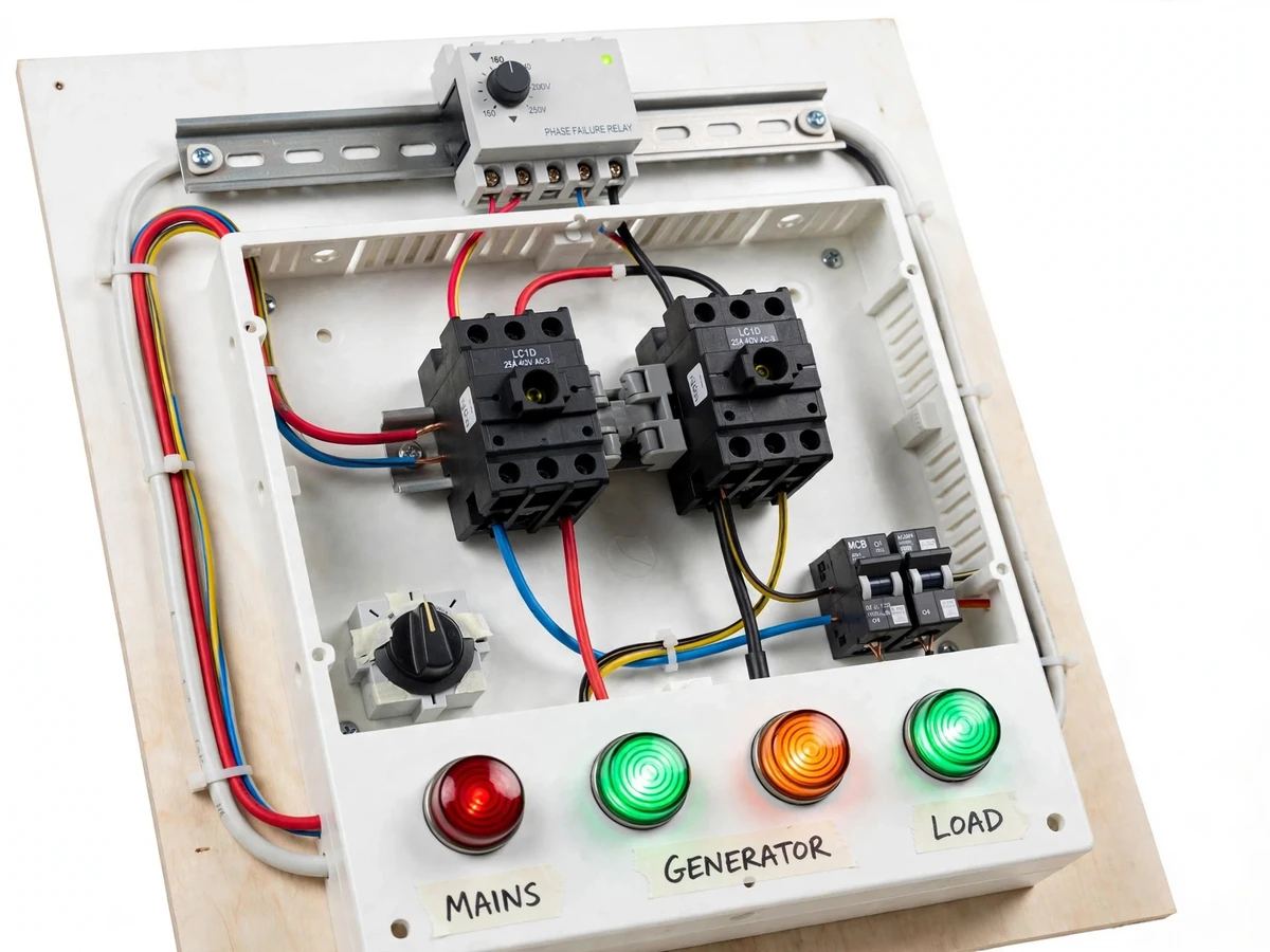
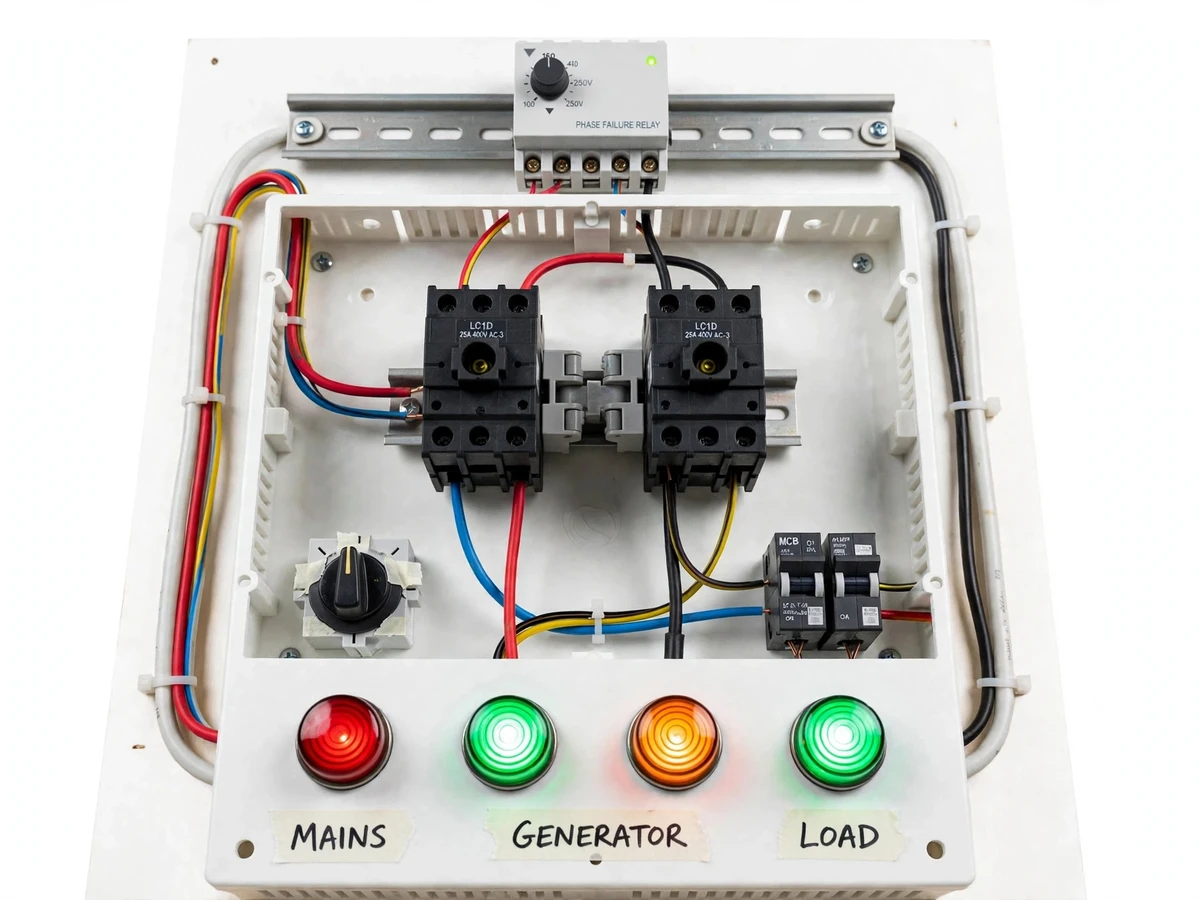
An automatic transfer switch, or ATS, is the panel that keeps a building powered when the mains supply disappears. In homes, workshops and college labs that run on a standby generator, someone has to notice the outage, walk to the generator, start it, and throw a manual changeover switch — and if one phase of a three-phase supply drops while the other two stay live, motors and three-phase loads keep running on two phases and overheat. This project builds an ATS panel that removes both gaps: a phase-failure monitoring relay watches all three mains phases for loss, undervoltage and wrong sequence, and on any fault it signals the generator to start, waits for its voltage to stabilise, and transfers the load through two mechanically interlocked contactors. When healthy mains returns, the panel transfers the load back and stops the generator after a cooldown delay. The result is a changeover that protects three-phase loads from single-phasing and keeps loads running.
Three-phase 415 V AC grid supply feeding the panel
Follow the working sequence
How it works
The panel works as a chain of sensing, decision, starting and switching. The phase-failure relay continuously measures all three mains phases; healthy mains keeps its output contact closed and the mains contactor energised, feeding the load from the grid. A lost phase, an undervoltage beyond the set threshold or a reversed sequence opens the relay contact, which the changeover logic reads as a mains failure. The logic then closes the generator-start dry contact, the generator cranks and builds voltage, and after an adjustable stabilisation delay the mains contactor drops out and the generator contactor closes, connecting the load to the generator. When mains returns and stays healthy through an adjustable retransfer delay, the generator contactor drops out, the mains contactor closes, and the generator receives a stop signal after a short cooldown run.
- The phase-failure relay continuously measures all three mains phases (L1, L2, L3) for voltage level, phase presence and phase sequence.
- Healthy mains keeps the relay output contact closed, the mains contactor energised, and the load fed from the grid through the mains MCB.
- On a mains failure or a lost phase, the relay contact opens; the changeover logic reads this as a mains failure and closes the generator-start dry contact, so the generator cranks and builds voltage.
- After an adjustable stabilisation delay of 0.1 to 30 seconds, the mains contactor drops out and the generator contactor closes, transferring the load to generator supply.
- Builder note from the build: the NC auxiliary contact of each contactor is wired into the other contactor's coil circuit before the selector switch, so even a welded contactor cannot back-feed the other source — the interlock wiring order is what makes the safety real, not the interlock bar alone.
- When mains returns, the relay watches it through an adjustable retransfer delay; only if it stays healthy does the generator contactor drop out and the mains contactor close, returning the load to the grid.
- The generator then receives a stop signal after a short cooldown run, and the panel returns to its normal mains-supplied state.
- In manual mode, the selector switch bypasses the automatic logic and the operator forces either source; the mechanical and electrical interlock still prevents both contactors closing together.
Tech stack:
- Schneider RM22TR33 phase-failure relay
- Schneider LC1D09 contactors · 230 V AC coil
- DIN-rail MCBs · 16 A control protection
- Manual/auto selector switch · 22 mm
- 22 mm indicator lamps · mains/generator/load
- 12 V DC generator start relay
- Copper wiring · 2.5 sq mm
- Mild-steel enclosure · IP54
| Parameter | Value |
|---|---|
| Supply monitored | 3-phase, 415 V AC, 50 Hz (design target) |
| Monitoring relay | Schneider RM22TR33 · 380–480 V AC range (datasheet) |
| Phase-failure detection | Voltage below 0.7 times nominal voltage (datasheet) |
| Threshold and delay | 2–20% of nominal voltage · 0.1–30 s adjustable (datasheet) |
| Main contactors | 2 × Schneider LC1D09 · 9 A AC-3 · 4 kW at 400 V AC (datasheet) |
| Contactor coil | 230 V AC, 50 Hz (datasheet) |
| Load capacity | Up to 4 kW three-phase (design target) |
| Generator start signal | Dry contact · 12 V DC relay output (design target) |
| Transfer time | Approximately 8–12 s from mains failure to generator supply (design target) |
| Enclosure | Approximately 400 × 300 × 150 mm · IP54 (design target) |
Project features
Automatic transfer between mains and generator is the core capability of this ATS panel: the mains contactor drops out on a fault and the generator contactor picks up only after the generator voltage is stable, so the load is never fed by two sources at once. Phase-failure protection is the second capability: the monitoring relay watches all three phases and treats a lost phase, a deep undervoltage or a reversed sequence as a mains failure, which is what stops single-phasing damage to three-phase motors. Generator auto-start and auto-stop is the third: a dry-contact signal cranks the generator on mains failure and shuts it down after a cooldown delay once mains returns. Manual override is the fourth: a selector switch lets the operator choose automatic or manual changeover and force either source during maintenance or testing.
- [Automatic mains-to-generator transfer] On a mains fault the panel drops the mains contactor and closes the generator contactor after a stabilisation delay, so the load moves to generator supply without anyone touching a switch. (Implemented)
- [Phase failure, undervoltage and sequence detection] The monitoring relay watches all three mains phases and treats a lost phase, a deep undervoltage or a reversed phase sequence as a mains failure, protecting three-phase loads from single-phasing. (Implemented)
- [Generator auto-start and auto-stop] A dry-contact output cranks the generator when mains fails and stops it after a cooldown delay once healthy mains returns, so the generator never runs longer than needed. (Implemented)
- [Mechanical and electrical interlock] A mechanical interlock bar between the two contactors plus cross-wired NC auxiliary contacts in each coil circuit make it physically impossible for both sources to connect to the load at the same time. (Implemented)
- [Adjustable transfer and retransfer delays] Transfer, stabilisation and retransfer delays are set on the relay and timer dials, so the panel can be tuned to the generator's crank time and to brief mains dips that should not trigger a changeover. (Configurable)
- [Manual/auto selector with source lamps] A rotary selector switch chooses automatic or manual changeover, and four indicator lamps show mains healthy, generator running, transfer in progress and load energised at a glance. (Implemented)
- [MCB protection for control and load circuits] Separate MCBs protect the control circuit and the load circuit, so a fault in one does not take down the other. (Implemented)
- [GSM alert on transfer] A GSM module can be added so the panel sends an SMS whenever it transfers to generator supply or back to mains. (Optional customization)
What is included
- Assembled ATS panel with two contactors, phase-failure relay, MCBs, selector switch and indicator lamps
- Wiring diagram and single-line diagram of the complete panel
- Generator start/stop interface wiring guide
- Test procedure covering mains failure, single-phase loss and mains return
- Project report PDF (background, protection theory, interlock design, methodology, results)
- PPT presentation for final review
- Viva Q&A preparation document (contactors, relays, interlocking, generator control)
Limitations & prerequisites
- Prototype is rated for loads up to 4 kW three-phase; larger loads need larger contactors and heavier wiring.
- Transfer time of approximately 8–12 seconds is a design target that depends on the generator's crank time; the panel cannot make a slow generator start faster.
- The panel is a demonstration prototype, not a certified installation; mains wiring must be done under qualified supervision.
- The generator must have an auto-start input; a generator without one cannot be started by this panel.
- The phase-failure relay detects loss, undervoltage and wrong sequence but does not correct voltage or frequency.
- Single-phase loads need a different contactor and relay arrangement than the three-phase build shown.
Frequently Asked Questions
Is this project suitable for a final-year project?
Yes — for Electrical Engineering and Electronics & Telecommunication students, this project is suitable because it demonstrates contactor control, protection relays, interlocking logic and generator control in one working panel. It covers power-system protection, control wiring and changeover logic, all core electrical subjects, and the demonstration is easy to show live: switch off a mains phase and the panel starts the generator and transfers the load.
What happens when the mains supply fails?
When mains supply fails completely, the phase-failure relay drops out, the panel closes the generator-start dry contact, and after the generator voltage stabilises the load transfers to generator supply. The whole sequence takes approximately 8 to 12 seconds, most of which is the generator's crank time. When mains returns and stays healthy through the retransfer delay, the load transfers back and the generator stops after a cooldown run.
What happens when only one phase fails?
When only one phase fails, the panel treats it exactly like a full mains failure: the phase-failure relay detects the missing phase and triggers the same generator start and transfer sequence. This matters because a three-phase motor running on two phases draws excess current and overheats, so the panel never leaves the load connected to a single-phased supply. The faulty phase is shown by the mains-healthy lamp going out.
How does the generator start automatically?
The generator starts automatically through a dry-contact output: when the relay declares a mains failure, a 12 V DC control relay closes a contact wired to the generator's auto-start input, which cranks the generator. No manual cranking or key turn is needed. The generator must have an auto-start or remote-start input for this to work; generators without one can only be started manually, in which case the panel still performs the transfer once the generator is running.
Can both sources ever connect to the load together?
No — both sources can never connect to the load together, because the panel uses two independent layers of interlocking. A mechanical interlock bar between the two contactors physically blocks one from closing while the other is closed, and the NC auxiliary contact of each contactor is wired into the other contactor's coil circuit, so an energised contactor electrically blocks its partner. Even a welded contactor cannot back-feed the other source.
Can the panel be demonstrated without a real generator?
Yes — the panel can be demonstrated without a real generator by using a lamp bank as the load and a simulated generator input, such as a second supply or a push-button start signal. The full sequence still shows: mains failure is simulated by switching off a phase, the start signal closes, the transfer happens after the stabilisation delay, and mains return transfers the load back. A real generator is needed only to show the actual crank and voltage build-up.
Components & software requirements
- Schneider RM22TR33 phase-failure relay
- Schneider LC1D09 contactors · 230 V AC coil
- DIN-rail MCBs · 16 A control protection
- Manual/auto selector switch · 22 mm
- 22 mm indicator lamps · mains/generator/load
- 12 V DC generator start relay
- Copper wiring · 2.5 sq mm
- Mild-steel enclosure · IP54
Delivery information
Built-to-order project. Delivery timeline is shared after order confirmation based on current queue.
Support terms
Complete documentation, setup guide, and viva preparation included. Support for setup and explanation provided.
Download free synopsis (PDF)
Enter your name and WhatsApp number — the synopsis PDF downloads immediately. We may send occasional project updates on WhatsApp; no spam.