
More project photos (2)

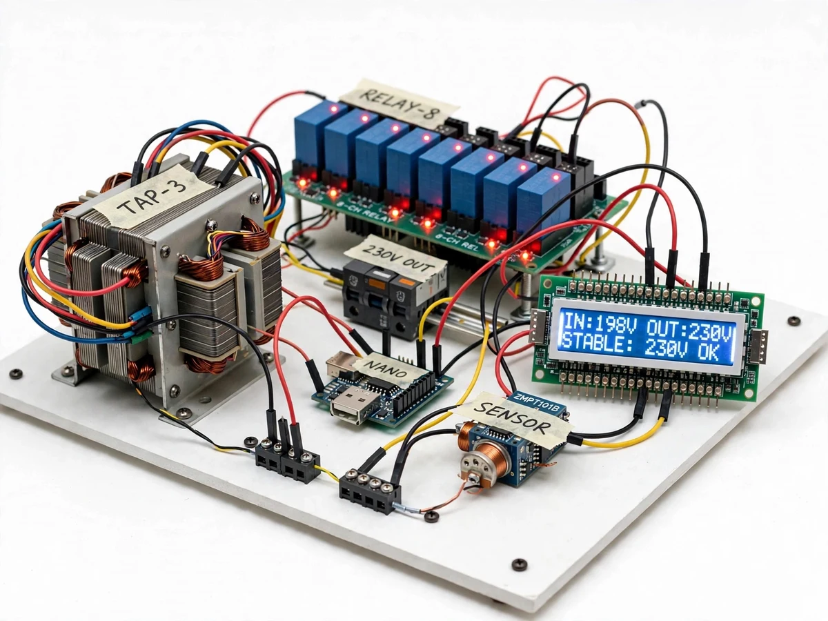
The problem
Mains voltage in many areas does not stay at 230 V — it sags during peak hours and surges at night, and appliances, lab equipment and project rigs all suffer when it does. Commercial stabilizers hide this problem behind a sealed box; students learn the concept without ever seeing how tap selection, voltage sensing or switching logic actually works. Servo-based stabilizers add a motor and carbon-brush assembly that is expensive and slow for a student build, while a fixed-tap transformer cannot adapt when the input moves. This project takes the practical middle path: a multi-tap auto transformer whose taps are switched by relays under microcontroller control, so the correction is automatic, fast and fully observable. The builder specifies the tap schedule, writes the tap-selection logic with hysteresis, and watches every decision on the LCD — input voltage, output voltage, active tap — which turns a black-box appliance into a teaching instrument.
230 V AC mains supply swinging across the input band.
Follow the working sequence
How it works
- Mains enters through the input terminals and a 6 A MCB, then reaches the common point of the 8-channel relay board and the multi-tap auto transformer.
- The ZMPT101B voltage-sensor module samples the input waveform continuously; the Arduino Nano reads it and computes the RMS input voltage.
- The firmware compares the measured voltage against the tap band table (8 bands spanning roughly 160–260 V, with ±5 V hysteresis around each boundary) and picks the tap whose ratio brings the output nearest 230 V.
- When the selected tap differs from the active one, the controller opens all relays for a short dead time (design ~50 ms), then energizes only the relay channel for the new tap — break-before-make, so two taps are never shorted.
- The transformer delivers the corrected voltage to the output terminals; the LCD continuously displays the input voltage, output voltage and the active tap number.
- If the input moves outside the correctable band (below ~140 V or above ~280 V, design targets), the firmware opens all relays, the output is disconnected, and the buzzer sounds until the input returns to a safe band.
- Tap thresholds, hysteresis and cut-off limits are stored as named constants in the firmware, so the behaviour can be re-tuned and re-verified during testing.
Tech stack:
- Arduino Nano (ATmega328P) + Arduino IDE firmware
- Multi-tap auto transformer (8 taps, 160–260 V band)
- 8-channel 5 V relay module (10 A · 250 VAC contacts)
- ZMPT101B AC voltage sensor module
- 16×2 I2C LCD (input/output voltage + active tap)
- 6 A single-pole MCB (input protection)
- Regulated 5 V/12 V DC supply (controller + relay coils)
- Buzzer + screw terminal blocks + enclosure hardware
| Parameter | Value |
|---|---|
| Input voltage range | 160–260 V AC, 50 Hz (design target) |
| Output voltage | 230 V AC nominal, ±5% (design target after calibration) |
| Taps | 8 (design), approximately 14 V per step |
| Relay contacts | 10 A / 250 VAC (datasheet rating, derated in design) |
| Voltage sensing | ZMPT101B module (±2% typical after calibration, datasheet) |
| Tap selection | Band table with ±5 V hysteresis (design) |
| Switching dead time | Approximately 50 ms, break-before-make (design) |
| Out-of-range cut-off | Below ~140 V or above ~280 V input (design targets) |
| Display | 16×2 LCD: input V, output V, active tap |
| Controller | Arduino Nano (ATmega328P) |
| Protection | 6 A MCB + secondary fuse (component ratings) |
| Transformer rating | 500 VA (component design spec) |
| Control power draw | Under 5 W (expected) |
Project features
- [Automatic relay tap switching] The Arduino Nano measures the input voltage continuously and energizes the relay channel for the tap that brings the output closest to 230 V — correction happens automatically as the mains swings, with no manual intervention.
- [Multi-tap auto transformer] A multi-tap auto transformer (8 taps across the 160–260 V input band, design target) provides the stepped correction; the tap schedule and turns-ratio reasoning are documented in the report for the viva.
- [Digital voltage display] A 16×2 LCD shows the measured input voltage, the output voltage and the currently active tap number, updating continuously so every switching decision is visible.
- [Hysteresis + dead-time switching] Tap changes use a ±5 V hysteresis band (design) plus a short all-relays-off dead time, so the controller never chatters between taps and never shorts two transformer sections together.
- [Out-of-range cut-off] If the input falls below ~140 V or rises above ~280 V (design targets), the firmware drops all relays, disconnects the output and raises a buzzer alarm instead of feeding an unsafe voltage to the load.
- [MCB and fuse protection] A 6 A MCB on the input and a secondary fuse give the hardware-level protection a mains installation needs; all protection ratings are component datasheet values.
- [Calibratable voltage sensing] The ZMPT101B sensor channel is calibrated against a known reference during assembly; the report documents the exact calibration procedure, which the buyer repeats with a multimeter.
- [Configurable tap thresholds] Tap band edges, hysteresis width and cut-off limits live as named constants in the firmware, so they can be re-tuned for a different input band without rewriting the logic.
What is included
- Working relay-based voltage stabilizer prototype (tap transformer, relay board, Arduino Nano, LCD, MCB, enclosure)
- Complete firmware source code with named tap-threshold constants
- Tap schedule and turns-ratio calculation document
- Circuit and wiring diagrams
- ZMPT101B calibration procedure (buyer-run, with multimeter)
- Project report PDF (background, transformer theory, methodology, test procedure)
- PPT presentation for final review
- Viva Q&A preparation document (tap changing, hysteresis, relay ratings, protection)
Limitations & prerequisites
- Relay switching is stepped, not continuous — the output moves in tap steps of about 14 V (design), so it regulates in bands rather than holding an exact 230.0 V.
- ±5% regulation and the 160–260 V band are design targets; the report documents a buyer-run variac test procedure to verify them on the built unit rather than claiming measured results.
- Relays have a finite mechanical life (datasheet: typically 100,000 electrical operations); rapid mains flicker wears contacts faster, which the hysteresis band mitigates but does not eliminate.
- This is an academic prototype, not a certified mains appliance — it is not BIS/ISI certified and must not be sold or installed as a commercial stabilizer.
- The 500 VA transformer rating is a component design spec; sustained load, ambient temperature and ventilation decide the real continuous rating.
- Output accuracy depends on correct sensor calibration; skipping the calibration procedure leaves the stated regulation targets unmet.
Frequently Asked Questions
Which controller is used and why?
An Arduino Nano (ATmega328P). Tap selection needs only a few analog reads, comparisons and digital outputs, so a larger board adds nothing — the Nano is inexpensive, well documented, and every line of the tap-logic firmware can be explained in a viva. The code is written in the Arduino IDE in plain C++, with no hidden libraries doing the thinking.
How is relay tap switching different from a servo stabilizer?
A servo stabilizer drives a motor and carbon brush along the winding for smooth correction, but it is slower, costlier and mechanically complex. This project switches discrete taps with relays: correction happens in steps within tens of milliseconds, the mechanism is fully visible, and the trade-off (stepped vs smooth output) is documented honestly in the report — strong viva material.
What load can the stabilizer handle?
The transformer is specified at 500 VA and the relay contacts are rated 10 A / 250 VAC (datasheet value, derated in the design). The practical continuous load depends on ventilation and duty; the report includes a buyer-run load-test procedure with a defined test load, and the protection (6 A MCB, fuse) is sized to the component ratings.
Does the voltage sensing need calibration?
Yes, once during assembly and verifiable any time after. The ZMPT101B channel is calibrated against a trusted multimeter reading following the documented procedure, and the firmware stores the calibration constant. Skipping calibration leaves the datasheet's uncalibrated tolerance, so the regulation targets assume this step is done.
Can the design be customized?
Realistic options: a different tap count or input band (re-specify the transformer and re-tune the firmware constants), a larger transformer rating, an LCD-to-OLED display swap, or an extended alarm scheme. Each is a defined hardware or firmware change, quoted separately — not a settings toggle.
Is this project suitable for a final-year project?
Yes — for Electrical Engineering programs. It demonstrates transformer tap theory and turns-ratio design, AC voltage sensing and RMS computation, relay switching logic with hysteresis and dead time, over/under-voltage protection, and calibration discipline — all on a working mains-voltage prototype. Suitable for B.E./B.Tech final-year projects in Electrical Engineering.
Components & software requirements
- Arduino Nano (ATmega328P) + Arduino IDE firmware
- Multi-tap auto transformer (8 taps, 160–260 V band)
- 8-channel 5 V relay module (10 A · 250 VAC contacts)
- ZMPT101B AC voltage sensor module
- 16×2 I2C LCD (input/output voltage + active tap)
- 6 A single-pole MCB (input protection)
- Regulated 5 V/12 V DC supply (controller + relay coils)
- Buzzer + screw terminal blocks + enclosure hardware
Delivery information
Built-to-order project. Delivery timeline is shared after order confirmation based on current queue.
Support terms
Complete documentation, setup guide, and viva preparation included. Support for setup and explanation provided.
Download free synopsis (PDF)
Enter your name and email — the synopsis PDF downloads immediately. We may send occasional project updates; no spam, unsubscribe anytime.