
More project photos (3)
The problem
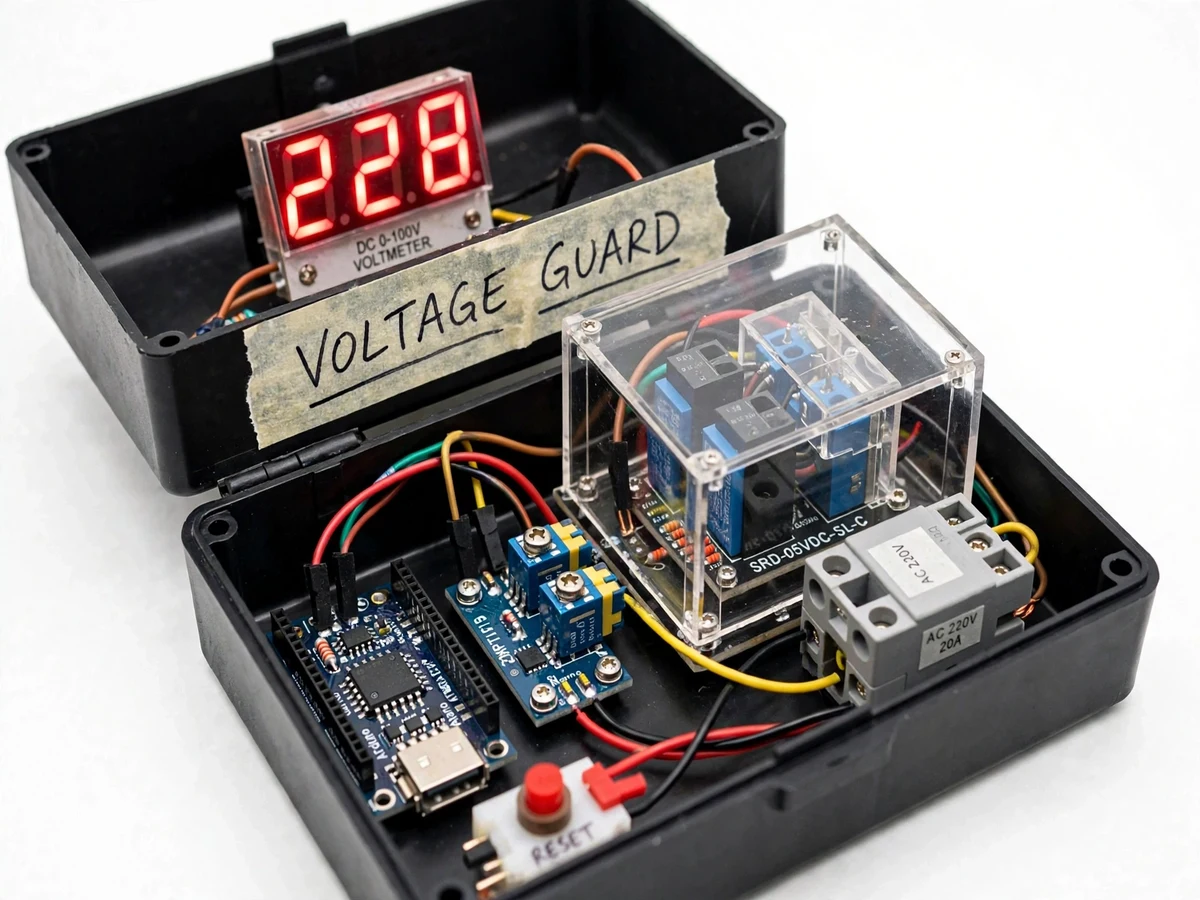
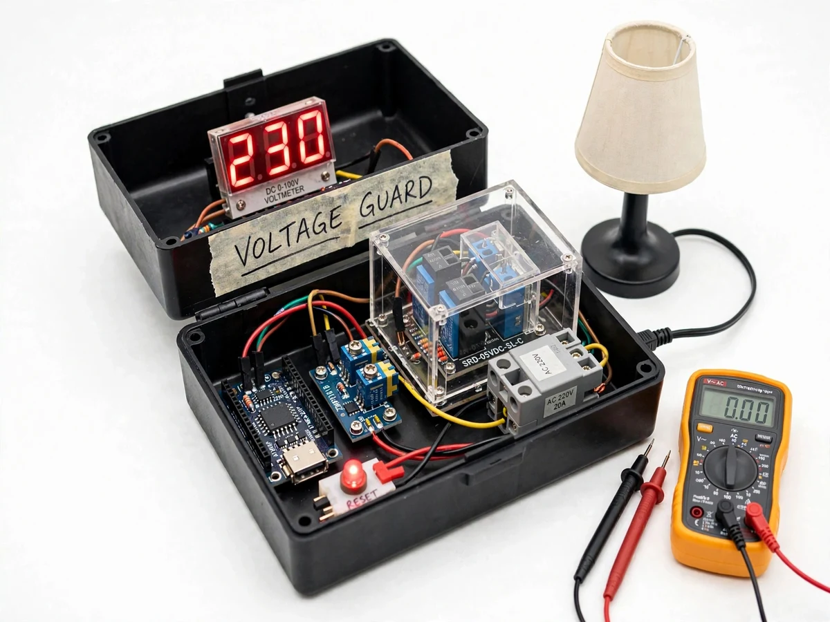
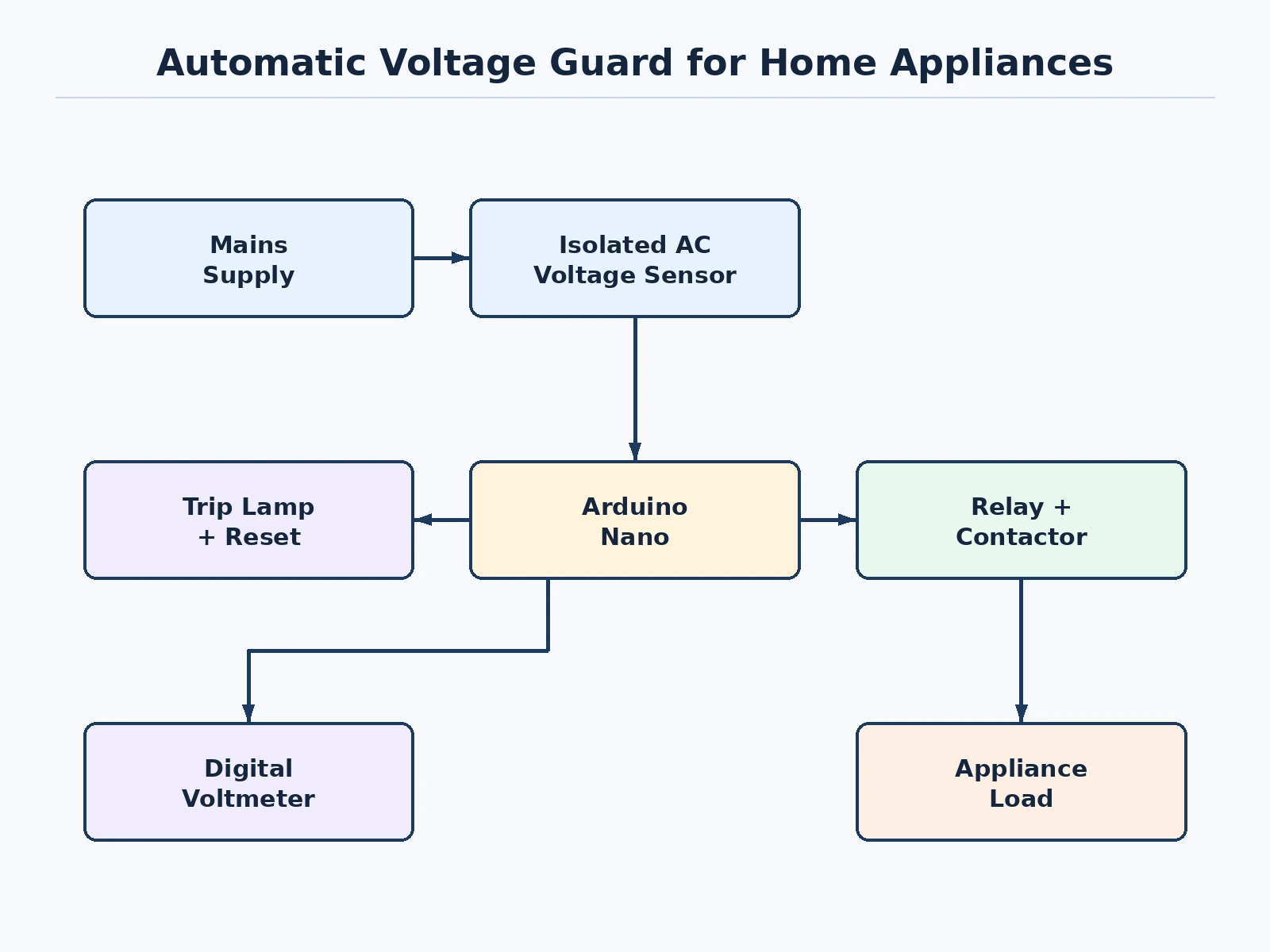
Every appliance nameplate carries a voltage rating, and every blown charger or dead fridge compressor in a voltage-fluctuation zone is what happens outside it. Commercial voltage guards exist but are sealed boxes; a student who builds one learns the full protection chain — isolated voltage sensing, RMS computation, threshold comparison with hysteresis, relay/contactor switching, and auto-reconnect timing. This project builds that chain as a transparent prototype: a ZMPT101B-class isolated voltage sensor feeds an Arduino, which computes the RMS line voltage, compares it against potentiometer-set over-voltage and under-voltage thresholds, and drives a relay module plus a power contactor to connect or disconnect the demo load. A digital voltmeter displays the line voltage live, a red lamp annunciates the tripped state, and a reset button re-arms the guard after a trip.
Transformer-isolated module senses the mains; its output is scaled into the Arduino ADC range.
Follow the working sequence
How it works
- The isolated sensor module is wired across the mains input; its low-voltage AC output is scaled and biased into the Arduino's ADC range.
- The firmware samples the waveform at high rate, computes the true RMS voltage each mains cycle, and smooths it with a short moving average.
- The RMS value is compared against the over-voltage and under-voltage thresholds set by the two trimmers, with hysteresis bands around each.
- If the voltage leaves the safe window for longer than the confirmation time, the Arduino drops the relay, the contactor opens, and the load is disconnected; the red trip lamp lights.
- When the voltage returns inside the window, the auto-reconnect timer runs; only after the full stabilization delay does the contactor re-close and restore the load.
- The student demonstrates all of this with a variable autotransformer (variac) sweeping the input voltage while the audience watches the voltmeter and the lamp.
Tech stack:
- Arduino Nano (ATmega328P)
- Isolated AC voltage sensor module (transformer-based)
- 5 V relay module + 230 V AC power contactor (20 A class)
- Digital panel voltmeter for live display
- Trimmer potentiometers for threshold setting
- Red trip-indicator lamp and reset push-button
- C/C++ firmware with RMS computation and hysteresis logic
- Enclosed prototype housing with shrouded mains terminals
| Parameter | Value |
|---|---|
| Input | 230 V AC nominal, 50 Hz (design) |
| Under-voltage trip | Adjustable, approximately 160–200 V (design) |
| Over-voltage trip | Adjustable, approximately 240–280 V (design) |
| Load rating | Up to approximately 20 A resistive (contactor datasheet) |
| Reconnect delay | Adjustable approximately 5–60 s (design) |
| Trip confirmation | Approximately 0.5–1 s sustained excursion (design) |
| Display | 3-digit digital voltmeter, approximately ±1% (expected) |
Project features
- [Isolated voltage sensing] A transformer-isolated sensing module measures the mains without any direct high-voltage connection to the low-voltage electronics — the safe way to sense AC line voltage.
- [True RMS computation] The firmware samples the waveform and computes RMS voltage, so the thresholds respond to the real heating value of the supply, not a peak estimate.
- [Adjustable over/under thresholds] Two trimmer potentiometers set the trip points (e.g. trip below ~180 V and above ~260 V), letting the student configure the guard for different appliance ratings.
- [Hysteresis on thresholds] Separate pick-up and drop-out levels stop the relay chattering when the voltage hovers at a threshold — a real protection-relay concept implemented in firmware.
- [Auto-reconnect timer] After the voltage returns to the safe band, the guard waits a configurable stabilization delay before reconnecting the load — protecting compressor motors from rapid cycling.
- [Live voltage display] A digital voltmeter shows the measured line voltage continuously, so the demo audience sees exactly what the guard is reacting to.
- [Manual reset and trip lamp] A red indicator shows the tripped state and a reset button re-arms the unit, demonstrating protection lockout behavior.
What is included
- Working automatic voltage guard prototype (sensing, control, switching, display)
- Arduino firmware with RMS computation, thresholds, hysteresis and auto-reconnect
- Threshold-calibration procedure using a variac and multimeter
- Wiring diagram and bill of materials
- Project report PDF (protection principles, sensing design, calibration results procedure)
- PPT presentation for final review
- Viva Q&A preparation document (RMS vs peak, hysteresis, contactor vs relay, auto-reconnect)
Limitations & prerequisites
- A single-phase guard for household-class loads; three-phase protection is listed as future scope.
- It protects against sustained over/under voltage, not against lightning surges or nanosecond transients — a surge protection device is a different product.
- Threshold calibration needs a variable autotransformer (variac), which the student's lab provides; the procedure documents the setup.
- The contactor has a finite electrical life (datasheet-rated operations); it is a demo unit, not a lifetime appliance accessory.
- Mains wiring is involved: the manual mandates qualified supervision and the prototype uses shrouded terminals and an enclosed housing.
- The voltmeter display is indicative (approximately ±1% expected), not a calibrated metering instrument.
Frequently Asked Questions
How is this different from a stabilizer?
A stabilizer corrects the voltage (buck/boost) and keeps the appliance running; a guard disconnects the appliance when voltage is unsafe and reconnects when it recovers. Guards are cheaper, simpler, and the standard protection for compressor loads.
Why does the reconnect need a delay?
Refrigerator and AC compressors are damaged by rapid on-off cycling (short-cycling). The stabilization delay — typically tens of seconds — lets pressures equalize before restart.
What is hysteresis and why is it in the firmware?
Without it, a voltage hovering exactly at the threshold would make the relay chatter on and off. Hysteresis uses separate trip and restore levels, a standard protection-relay technique.
Is it safe for a student to build with mains voltage?
The design keeps all mains inside a shrouded, enclosed section and senses through an isolated transformer module; the manual still mandates qualified supervision for any mains work.
What load can it switch?
The contactor is 20 A class (datasheet), which covers typical household appliances — fridge, TV, washing machine — one at a time in the demo.
Is this project suitable for a final-year project?
Yes — for Electrical and Electronics programs. It demonstrates protection principles, isolated sensing, embedded firmware and a real calibration procedure. Suitable for B.E./B.Tech final-year projects in Electrical and Electronics.
Components & software requirements
- Arduino Nano (ATmega328P)
- Isolated AC voltage sensor module (transformer-based)
- 5 V relay module + 230 V AC power contactor (20 A class)
- Digital panel voltmeter for live display
- Trimmer potentiometers for threshold setting
- Red trip-indicator lamp and reset push-button
- C/C++ firmware with RMS computation and hysteresis logic
- Enclosed prototype housing with shrouded mains terminals
Delivery information
Built-to-order project. Delivery timeline is shared after order confirmation based on current queue.
Support terms
Complete documentation, setup guide, and viva preparation included. Support for setup and explanation provided.
Download free synopsis (PDF)
Enter your name and WhatsApp number — the synopsis PDF downloads immediately. We may send occasional project updates on WhatsApp; no spam.