
More project photos (3)
The problem
Power cuts still interrupt study, work and basic home lighting, and the inverters most homes rely on are sealed commercial boxes that students never get to open. Cheap square-wave units also run hot on some loads and make fans hum, while a pure sine wave output is cleaner but harder to generate — it needs precisely timed SPWM switching, a proper H-bridge with dead-time, and a transformer plus LC filter sized for the load. A second gap is battery care: a 12V lead-acid battery pulled below about 10.5V suffers deep discharge that permanently shortens its life, yet most student inverter builds have no automatic cutoff at all. This project closes both gaps in one build — a microcontroller-driven SPWM H-bridge producing 230V pure sine AC from a 12V battery, guarded by an automatic low-voltage cutoff with re-connect hysteresis, overload protection and a mains-sensing changeover relay.
12 V lead-acid battery feeding the H-bridge DC bus through the cutoff relay.
Follow the working sequence
How it works
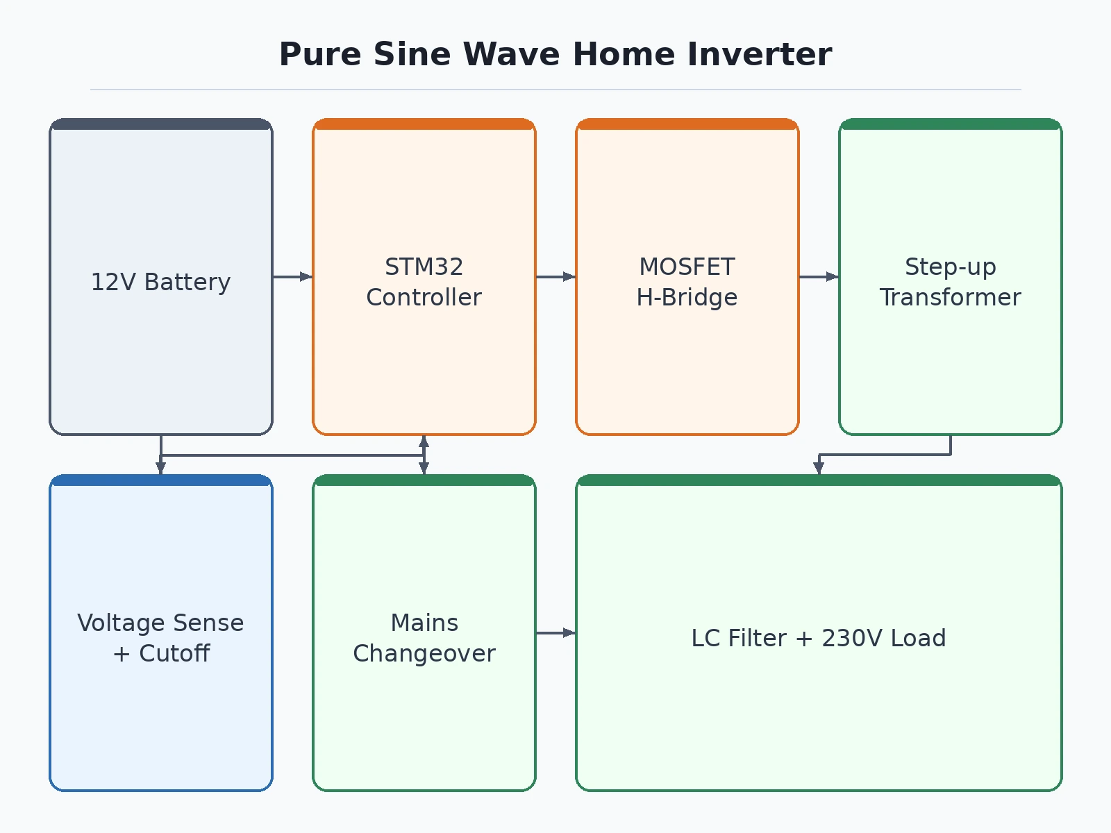
- The 12V lead-acid battery feeds the H-bridge DC bus through the cutoff relay, which stays closed while the battery voltage is healthy.
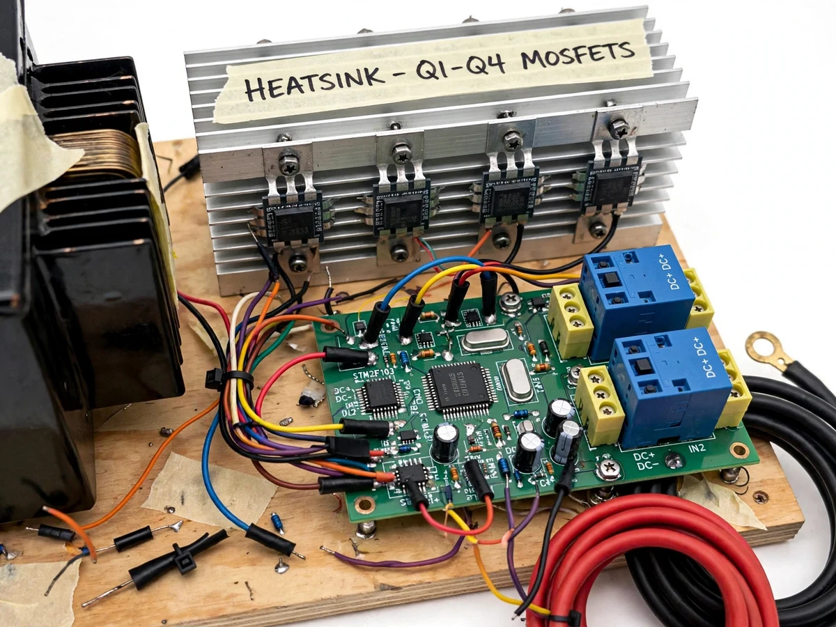
- The STM32F103C8T6 generates complementary SPWM at a carrier near 16kHz (design target) with a 50Hz fundamental, driving the four IRF540N MOSFETs through gate-drive circuitry with dead-time to prevent shoot-through.
- The H-bridge output passes through the LC filter and the EI-core step-up transformer, emerging as approximately 230V AC at 50Hz.
- The controller samples the battery voltage continuously; when it drops near the 10.5V cutoff (design target), the SPWM drive is disabled and the cutoff relay opens, isolating the battery.
- The battery is re-connected only after it recovers near 11.5V (design-target hysteresis), preventing relay chatter at the threshold.
- A mains-sensing circuit watches the grid: with mains present the changeover relay routes the load to mains, and on mains failure it switches the load to the inverter output.
- Output current is monitored continuously — a sustained overload or short circuit shuts down the SPWM drive and latches a fault LED until manual reset.
Tech stack:
- STM32F103C8T6 microcontroller (SPWM generation + cutoff and changeover logic)
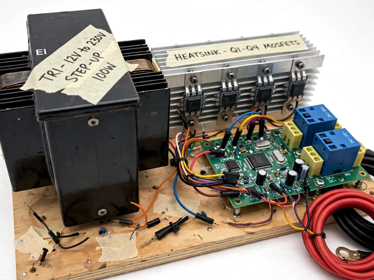
- IRF540N N-channel MOSFETs ×4 in full H-bridge on a shared heatsink
- EI-core step-up transformer (12V centre-tapped primary to 230V secondary)
- LC output filter for sine shaping
- Relay-based automatic mains changeover with mains sensing
- C/C++ firmware (STM32CubeIDE / Arduino-core build)
- 12V lead-acid battery system with fused ring-terminal cables
- Multimeter + oscilloscope for calibration and waveform verification
| Parameter | Value |
|---|---|
| DC input | 12V lead-acid battery (buyer-procured; fused ring-terminal cables supplied) |
| Output voltage | 230V AC, 50Hz (design target) |
| Continuous power | Approximately 100W (design target) |
| Waveform | Pure sine wave via SPWM + LC filter (design target; buyer verifies on oscilloscope) |
| Inverter topology | Full H-bridge, 4 × IRF540N N-channel MOSFETs |
| MOSFET ratings | Vds 100V, Rds(on) 44mΩ max at Vgs = 10V, Id 33A at 25°C (datasheet values) |
| Controller | STM32F103C8T6 generating complementary SPWM with dead-time |
| SPWM carrier | Approximately 16kHz (design target); 50Hz fundamental |
| Transformer | EI-core step-up, 12V centre-tapped primary to 230V secondary, approximately 100VA (design target) |
| Low-voltage cutoff | 10.5V typical (design target; standard 0%-SoC reference for 12V lead-acid) |
| Re-connect voltage | Approximately 11.5V (design-target hysteresis) |
| Changeover | Relay-based automatic mains/inverter switching with brief switchover gap (expected) |
| Protections | Overload/short-circuit shutdown with manual reset; battery low-voltage cutoff (implemented) |
| Conversion efficiency | Approximately 80–85% at rated load (design target, not measured) |
Project features
- [Pure sine wave 230V output] An SPWM-driven four-MOSFET H-bridge feeds an EI-core step-up transformer and LC filter to produce 230V AC at 50Hz — a cleaner waveform than square-wave student builds, sized for small home loads. (Implemented; approximately 100W continuous is a design target, not a measured claim.)
- [Automatic battery low-voltage cutoff] The controller continuously measures battery voltage and disconnects the inverter when it falls near 10.5V — the standard 0%-SoC reference for 12V lead-acid — preventing the deep discharge that permanently damages batteries. (Implemented; the cutoff point is a design target.)
- [Re-connect hysteresis] After a cutoff, the inverter re-arms only when the battery recovers near 11.5V, so the changeover relay never chatters at the threshold. (Implemented; 11.5V is a design target.)
- [Automatic mains changeover] A mains-sensing relay keeps the load on grid power while mains is present and switches it to the inverter on mains failure. (Implemented; there is a brief relay switchover gap, so this is not a zero-transfer online UPS.)
- [Overload and short-circuit protection] Output current sensing shuts down the H-bridge drive on sustained overload or a shorted output, with manual reset required before restart. (Implemented; the trip threshold is firmware-configurable.)
- [Mains, battery and fault status indication] On-board LEDs show at a glance whether the load runs on mains or battery, and flag cutoff or overload faults. (Implemented.)
- [Optional mains charger integration] A charger module can be added on request so the same mains path tops up the battery whenever grid power is present. (Optional customization — not part of the base build.)
What is included
- Working inverter prototype: control board, MOSFET H-bridge on heatsink, step-up transformer, changeover relay section, wired on a wooden base
- Firmware source code (STM32: SPWM generation, cutoff logic, changeover sequencing)
- Circuit schematic and point-to-point wiring diagram
- Component list with part numbers and suggested ratings
- Cutoff calibration and oscilloscope test procedure for the buyer to verify their own build
- Project report PDF, PPT presentation and viva Q&A document
- Demonstration guidance for the final review
Build timeline
- Built-to-order in approximately 3–4 weeks from order confirmation (expected): component procurement and board assembly, firmware and wiring, then testing, cutoff calibration and documentation.
Support
- Remote build guidance and viva-preparation support during the semester; documentation queries answered against the supplied report and test procedures. Component damage from misuse or unsupervised mains work is excluded.
Limitations & prerequisites
- Academic prototype, not a certified UPS — no claim of ISI/IEC certification or grid-code compliance.
- 230V AC mains wiring and testing must be done under qualified supervision; mains voltage is lethal and the prototype is open-frame.
- Approximately 100W continuous (design target) — suits LED lamps, fans and chargers, not refrigerators, air-conditioners or motors with large inrush currents.
- Efficiency, waveform purity and exact voltage regulation are design targets, not measured claims; the buyer verifies waveform and voltage on their own build with the included procedure.
- The 12V lead-acid battery is buyer-procured (type and terminals specified); battery capacity and condition strongly affect backup time.
- The relay changeover has a brief switchover gap — sensitive equipment may reset; this is not a zero-transfer online UPS.
- Repeated deep cycling still ages a lead-acid battery; the cutoff reduces abuse but does not make the battery immortal.
Frequently Asked Questions
Which MOSFET is used in the H-bridge, and why?
Four IRF540N N-channel MOSFETs form the full H-bridge. The datasheet rates them at 100V drain-source breakdown, 44mΩ maximum on-resistance at 10V gate drive and 33A continuous drain current at 25°C — comfortable margins on a 12V battery bus for a 100W design target. They are cheap, widely available in TO-220 packages and bolt directly to a shared heatsink, which keeps the student build serviceable.
What is the low-voltage cutoff, and can it be adjusted?
The cutoff sits near 10.5V as a design target — the standard 0% state-of-charge reference for a 12V lead-acid battery — and the inverter re-arms near 11.5V so the relay never chatters at the threshold. Both points are firmware constants, so they can be shifted within a safe band during calibration, for example to cut off earlier and trade backup time for longer battery life.
Can this inverter run a whole house?
No. The prototype targets approximately 100W continuous — enough for LED lamps, a fan and phone chargers during a power cut, but not refrigerators, air-conditioners or pumps with heavy starting surges. A larger rating is possible as an optional customization with a bigger transformer, a heavier MOSFET stage and a higher-capacity battery, quoted separately.
Is this project suitable for a final-year project?
Yes, for Electrical Engineering and related programs. It demonstrates power-electronic switching with SPWM, H-bridge gate drive with dead-time, magnetic component sizing in the step-up transformer, battery management through the low-voltage cutoff, and protection coordination with overload shutdown and mains changeover — rich material for viva discussion.
What safety precautions apply while building and testing?
Treat it as mains equipment from day one: 230V AC is lethal, so mains-side wiring, transformer secondary connections and all live testing happen under qualified supervision, with the unit unplugged during assembly. The prototype is open-frame and uncertified, so it must never be left powering loads unattended, and the battery leads are fused against accidental shorts.
Components & software requirements
- STM32F103C8T6 microcontroller (SPWM generation + cutoff and changeover logic)
- IRF540N N-channel MOSFETs ×4 in full H-bridge on a shared heatsink
- EI-core step-up transformer (12V centre-tapped primary to 230V secondary)
- LC output filter for sine shaping
- Relay-based automatic mains changeover with mains sensing
- C/C++ firmware (STM32CubeIDE / Arduino-core build)
- 12V lead-acid battery system with fused ring-terminal cables
- Multimeter + oscilloscope for calibration and waveform verification
Delivery information
Built-to-order project. Delivery timeline is shared after order confirmation based on current queue.
Support terms
Complete documentation, setup guide, and viva preparation included. Support for setup and explanation provided.
Download free synopsis (PDF)
Enter your name and email — the synopsis PDF downloads immediately. We may send occasional project updates; no spam, unsubscribe anytime.