
More project photos (2)
The problem
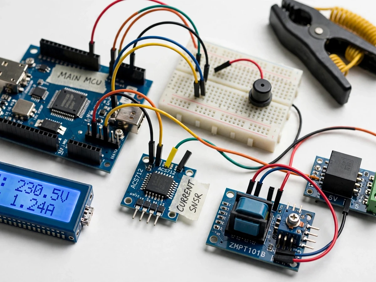
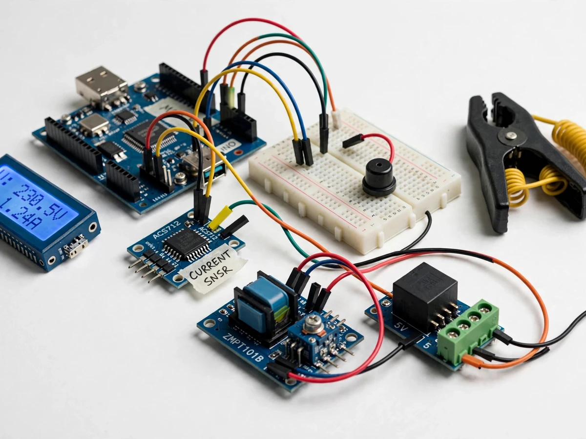
A conventional meter only reveals the total at month's end. Students studying energy measurement need to see what happens between the wall socket and the dial: how voltage and current are actually sensed, how instantaneous power becomes billable energy, and how a limiter acts when a load crosses a set threshold. This project closes that gap with a small, honest prototype. An Arduino reads mains voltage through a ZMPT101B transformer module and load current through an ACS712 Hall-effect sensor, computes true RMS values in firmware, integrates energy in kilowatt-hours, and multiplies by a configurable tariff to show a live billing estimate on a 16x2 LCD. When current stays above a user-set limit for the configured confirmation time, a relay disconnects the load after a buzzer warning, demonstrating how utilities and institutions enforce load limits. Both sensing stages are galvanically isolated from the controller.
Steps mains voltage down through an isolation transformer and outputs a small AC waveform for the Arduino ADC.
Follow the working sequence
How it works
- The ZMPT101B module reduces mains voltage through its isolation transformer and outputs a small AC waveform centered on a 2.5 V DC offset to one Arduino ADC channel; the ACS712 outputs an analog voltage centered on 2.5 V, proportional to instantaneous load current, to another channel.
- Firmware samples both channels across each 20 ms mains cycle, subtracts the offset, and computes true RMS voltage and RMS current.
- Instantaneous power (Vrms x Irms) is integrated over time into kilowatt-hours; the kWh total is multiplied by the stored tariff to produce the billing estimate shown on the LCD.
- In parallel, the firmware compares RMS current with the stored limit; crossing it starts a confirmation timer and sounds the buzzer.
- If current is still above the limit when the timer expires, the controller de-energizes the relay, the load is disconnected, and the LCD shows LIMIT TRIPPED until a manual reset button is pressed.
- Limit and tariff are edited with push buttons through a simple LCD menu; the EEPROM library saves them so settings persist across power cycles.
Tech stack:
- Arduino Uno (ATmega328P)
- ZMPT101B voltage transformer module
- ACS712 Hall-effect current sensor (5A variant)
- 16x2 character LCD (HD44780)
- 5V single-channel relay module
- Active buzzer, push buttons
- Arduino IDE, C/C++ firmware
- EEPROM library for settings storage
| Parameter | Value |
|---|---|
| Mains voltage input | Up to 250 V AC RMS, 50 Hz (datasheet, ZMPT101B module) |
| Current measurement range | +/-5 A (datasheet, ACS712-05B; 20 A/30 A variants supported) |
| Current sensitivity | 185 mV/A (datasheet, ACS712-05B) |
| Sensor output level | Analog, centered on 2.5 V at zero input (datasheet) |
| Controller | Arduino Uno, ATmega328P, 5 V, 16 MHz (datasheet) |
| ADC resolution | 10-bit, 0-5 V input range (datasheet, ATmega328P) |
| Relay contacts | 10 A / 250 V AC (datasheet, relay module) |
| Display | 16x2 character LCD with backlight (module standard) |
| RMS refresh rate | Approximately 1 reading per second (design target) |
| Over-limit confirmation time | 2-10 s, user-settable (firmware) |
| Energy display resolution | 0.001 kWh (design target) |
Project features
- [Live voltage and current sensing] The ZMPT101B transformer module measures mains voltage while the ACS712 Hall-effect module measures load current; both feed Arduino ADC channels so students see real mains quantities converted into readings.
- [True RMS computation in firmware] Firmware samples both channels over each mains cycle and computes RMS voltage and current, so the power figure responds honestly to sagging or rising supply instead of assuming a fixed 230 V.
- [Load-limit relay cutoff] The current limit is stored in the controller; when measured current stays above it through the confirmation window, a 5 V relay module disconnects the load, and the system re-arms only on manual reset.
- [Pre-trip buzzer warning] An active buzzer sounds before the cutoff, so the demo visibly warns ahead of tripping — the same sequence real demand limiters follow.
- [Live kWh and billing display] The LCD cycles through voltage, current, instantaneous power, cumulative kWh and the estimated bill at the configured tariff — the billing part of the brief, implemented on hardware.
- [Configurable limit and tariff] On-board push buttons set the current limit and the Rs/kWh tariff without reflashing; values are kept in EEPROM so they survive power cycles.
- [Galvanic isolation] Both sensor modules isolate the mains side from the Arduino, and the relay module separates coil from contacts, following standard student-lab safety practice.
- [Buyer-run calibration procedure] The ZMPT101B trim potentiometer and firmware constants come with a documented step-by-step calibration against a reference meter, so readings are verified on the student's own build.
What is included
- Working smart energy meter prototype (Arduino Uno, ZMPT101B module, ACS712 sensor, 16x2 LCD, relay module, buzzer, buttons, wired on a base board)
- Complete Arduino firmware (dual-channel sampling, RMS math, limit logic, LCD menu, EEPROM storage)
- Wiring diagram and pin connection table
- Calibration procedure document (trim-pot adjustment and firmware constants vs a reference meter)
- Project report PDF (background, sensor theory, methodology, calculations, results template)
- PPT presentation for final review
- Viva Q&A preparation document (RMS, Hall effect, isolation, energy math, relay sizing)
Limitations & prerequisites
- Energy accuracy is a design target of +/-5% after buyer-run calibration — not a measured or certified figure; the report records the student's own calibration readings.
- Power is computed as Vrms x Irms with power factor assumed 1.0; reactive loads will read high. The assumption is stated on the page and a firmware PF constant is buyer-adjustable.
- The ACS712-05B caps measurable current at +/-5 A; loads above that need the 20 A or 30 A variant (supported by changing one sensitivity constant).
- The relay module is rated 10 A / 250 V AC — the prototype is sized for demo loads, not for switching a whole house.
- Mains wiring is involved: assembly and first power-up must be supervised, with insulated connections and a fused supply. The kit is a teaching prototype, not a revenue-grade or certified meter.
- The tariff is a single flat user-set rate; slab-based billing is not implemented.
Frequently Asked Questions
How does the load limiting work?
You set a current limit with the on-board buttons. The firmware watches RMS current continuously; crossing the limit starts a short confirmation timer and sounds the buzzer. If the overload is still present when the timer expires, the relay drops the load and the LCD shows LIMIT TRIPPED until you press the reset button. Brief spikes shorter than the timer are ignored, matching real limiter behavior.
How is the billing figure calculated?
Firmware integrates instantaneous power (Vrms x Irms) over time to get kilowatt-hours, then multiplies by the tariff you set in Rs/kWh. It is an estimate, not a utility reading: power factor is assumed 1.0 unless you change the constant, and accuracy depends on the calibration you run against a reference meter. It demonstrates the full energy-to-billing chain.
Which current sensor does it use, and what are its ratings?
The default build uses the ACS712-05B Hall-effect module: +/-5 A range, 185 mV/A sensitivity, 5 V supply, galvanically isolated output centered at 2.5 V with no current. If the demo load exceeds 5 A, the firmware supports the 20 A (100 mV/A) and 30 A (66 mV/A) variants with a single constant change.
Is it safe to wire to household mains?
Both sensor modules are galvanically isolated from the Arduino and the relay module separates coil from contacts, but you are still working with 230 V AC. Assembly and first power-up should be supervised, all connections insulated and fused, and the prototype treated as a lab demonstrator — not a certified installation or revenue meter.
Can the limit and tariff be changed without reprogramming?
Yes. Two push buttons open a small LCD menu for setting the current limit and the Rs/kWh tariff; values are written to the Arduino EEPROM and survive power cycles. That is how the demo is adapted — for example, a lower limit for a heater demo, or the local tariff so the billing estimate matches the student's region.
Is this project suitable for a final-year project?
Yes — for Electrical (and E&TC) programs. It covers sensing, signal conditioning, RMS measurement, firmware logic, load control and the energy-to-billing chain in one build, all on hardware the student can demonstrate live and fully defend question-by-question in the viva.
Components & software requirements
- Arduino Uno (ATmega328P)
- ZMPT101B voltage transformer module
- ACS712 Hall-effect current sensor (5A variant)
- 16x2 character LCD (HD44780)
- 5V single-channel relay module
- Active buzzer, push buttons
- Arduino IDE, C/C++ firmware
- EEPROM library for settings storage
Delivery information
Built-to-order project. Delivery timeline is shared after order confirmation based on current queue.
Support terms
Complete documentation, setup guide, and viva preparation included. Support for setup and explanation provided.
Download free synopsis (PDF)
Enter your name and email — the synopsis PDF downloads immediately. We may send occasional project updates; no spam, unsubscribe anytime.