
More project photos (2)
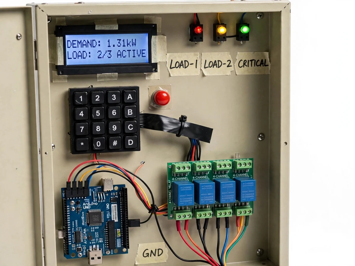

The problem
Industrial electricity bills have two parts: energy consumed (kWh) and maximum demand (kW) — the highest average load recorded over a demand interval, usually 15 or 30 minutes. Exceed the contracted demand even once and the penalty applies for months, so plants install maximum demand controllers that watch the load trend and shed non-critical loads before the limit is crossed. Students learn the tariff structure in power systems courses but rarely see the controller logic working: the demand computation, the warning stage, the priority-ordered tripping and the restoration sequence. This project builds a bench-scale version — current sensors on a simulated feeder, three switchable load stages, a keypad for the demand setpoint, and a relay bank that trips loads lowest-priority-first with a pre-trip warning — so the full penalty-avoidance logic runs visibly. Every design decision, from the demand-averaging window to the trip/restore hysteresis, is documented and defensible.
How it works
- Current sensors on the simulated feeder measure each load branch; the Arduino sums them into total instantaneous demand in watts.
- The demand setpoint entered on the keypad is stored in EEPROM and compared against live demand every second.
- When demand crosses 90% of the setpoint, the warning stage fires — buzzer plus flashing lamp — inviting manual load reduction.
- If demand reaches 100% of the setpoint, the controller trips the lowest-priority load via its relay, re-checks demand after a short settling delay, and trips the next load if still over the limit.
- The highest-priority (critical) load is never tripped automatically — the firmware treats it as protected, mirroring real plant practice.
- When demand drops below the setpoint minus a hysteresis band, a restoration timer starts; on expiry, tripped loads are restored one at a time in reverse priority order.
- Every warning, trip and restoration is logged with a timestamp on the LCD event log for the demonstration and the report.
Tech stack:
- Arduino Uno (ATmega328P) controller
- Hall-effect / CT current sensors per load branch
- 4-channel relay bank for load switching
- 4×4 matrix keypad + 16×2 LCD with I2C backpack
- Buzzer + panel warning lamps
- Lamp/heater load bank (3 priority stages)
- 230 V AC to 5 V/12 V power supplies, enclosure wiring
- EEPROM setpoint storage, hysteresis trip/restore firmware logic
| Parameter | Value |
|---|---|
| Demand measurement | 3 load branches, summed in firmware |
| Setpoint range | Approximately 100–1500 W (design target, scaled demo) |
| Warning threshold | 90% of setpoint (fixed in firmware) |
| Restore hysteresis | Setpoint minus approximately 10% (design target) |
| Trip settling delay | Approximately 5 s between successive trips (design) |
| Restoration delay | Approximately 30 s after demand falls (design target) |
| Load stages | 3 (low / medium / critical-protected) |
| Display | 16×2 LCD: live demand, setpoint, status, event log |
Project features
- [Live demand measurement] Current sensors on each load branch feed an Arduino that computes total feeder demand continuously, displayed in watts on the LCD.
- [Keypad-set demand limit] The maximum demand setpoint is entered on a 4×4 keypad and stored in EEPROM, with the set value shown alongside live demand.
- [90% pre-warning stage] A buzzer and flashing warning lamp activate when demand crosses 90% of the limit, giving the operator a chance to shed load manually.
- [Priority-ordered load tripping] On breaching the limit, the controller trips loads lowest-priority-first through a relay bank, with each trip and its timestamp shown on the display.
- [Automatic restoration] When demand falls below the restore threshold (limit minus hysteresis), tripped loads are switched back in reverse order after a time delay.
- [Three load stages] Lamp/heater load bank simulating industrial load mix — e.g. lighting (low priority), process heater (medium), critical drive (never tripped).
- [Event log on display] Scrollable log of the last warnings, trips and restorations with elapsed-time stamps for the demonstration.
What is included
- Complete maximum demand controller panel with load bank
- Arduino firmware (demand computation, warning, trip/restore logic, event log)
- Wiring diagram and panel layout drawing
- Demand-tariff background note explaining kW vs kWh billing
- Test procedure: stepped-load demonstration script with expected sequence
- Project report PDF (background, tariff theory, design, firmware logic, test results)
- PPT presentation for final review
- Viva Q&A preparation document (demand interval, penalties, hysteresis, priority shedding)
Limitations & prerequisites
- Bench-scale demonstration at approximately 100–1500 W — the control logic is identical to industrial units but the power level is scaled for a lab bench.
- Uses instantaneous-demand comparison rather than a true 15/30-minute sliding demand interval; the report explains the interval concept and why the demo simplifies it.
- Current sensing is single-phase on the demo feeder; a real three-phase installation needs three-phase power measurement, noted as an extension.
- Trip timings and hysteresis values are design targets chosen for a visible demo — the buyer verifies the actual sequence timing on their build with the supplied test script.
- Not a revenue-grade or utility-approved device; it demonstrates the control principle for academic purposes.
Frequently Asked Questions
What is maximum demand and why does it matter?
It is the highest average load (kW) recorded over a demand interval (typically 15–30 minutes). Utilities bill it separately from energy, and breaching the contracted demand triggers penalties that can persist for months — which is why industries install controllers that shed load automatically.
How does the controller decide which load to trip?
Loads are assigned priorities at wiring time (low/medium/critical). On breaching the setpoint, the firmware trips the lowest-priority load first, waits a settling delay, re-checks demand, and only then trips the next — the critical load is never auto-tripped.
Why is there a warning stage before tripping?
Real controllers warn first so operators can shed load manually. The 90%-of-setpoint buzzer and lamp replicate that, and the report explains how the warning window maps to operator response time in plants.
What stops the loads from chattering on and off at the limit?
A hysteresis band plus time delays: restoration only begins when demand falls about 10% below the setpoint and stays there for the restoration delay, so the relays do not oscillate.
Can the demand limit be changed without reprogramming?
Yes — the setpoint is entered on the keypad and stored in EEPROM, so it survives power cycles and needs no code change.
Is this project suitable for a final-year project?
Yes — for Electrical Engineering programs. It connects tariff theory from power systems to a working protection-against-penalty controller with real firmware logic to defend in the viva. Suitable for B.E./B.Tech final-year projects in Electrical Engineering.
Components & software requirements
- Arduino Uno (ATmega328P) controller
- Hall-effect / CT current sensors per load branch
- 4-channel relay bank for load switching
- 4×4 matrix keypad + 16×2 LCD with I2C backpack
- Buzzer + panel warning lamps
- Lamp/heater load bank (3 priority stages)
- 230 V AC to 5 V/12 V power supplies, enclosure wiring
- EEPROM setpoint storage, hysteresis trip/restore firmware logic
Delivery information
Built-to-order project. Delivery timeline is shared after order confirmation based on current queue.
Support terms
Complete documentation, setup guide, and viva preparation included. Support for setup and explanation provided.