
More project photos (2)
The problem
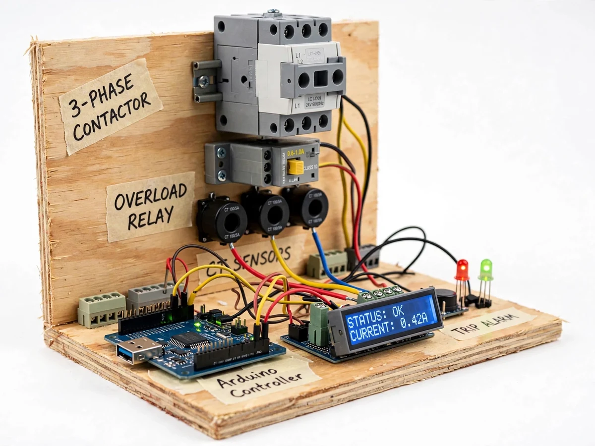
Three-phase induction motors burn out far more often from supply faults than from age: lose one phase and the motor keeps running on two, drawing up to √3 times the current in the remaining windings until the insulation cooks. Overload is slower but just as fatal, and overheating from blocked ventilation finishes the job. Standard practice in industry is a motor protection panel — contactor plus thermal overload relay — but students rarely get to design one, and textbook chapters on protection curves never show how a single-phasing event actually gets detected and converted into a trip command. This project builds that panel as a complete student prototype: phase-loss sensing on the supply, CT-based current sensing on all three phases, winding temperature sensing, an Arduino controller that makes the trip decision, and a contactor that cuts the motor on a confirmed fault.
Three sensing circuits (transformer, rectifier, opto-isolator) giving a live digital signal per supply phase.
Follow the working sequence
How it works
- Three phase-loss sensing circuits (230 V → low-voltage transformer, rectifier, opto-isolator) give the controller a live digital signal for each supply phase.
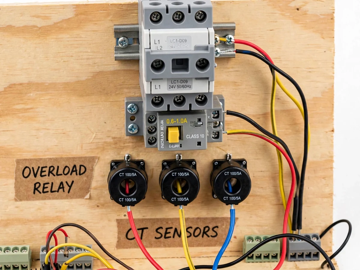
- Three 100/5 A-class ring CTs carry the motor's phase conductors; burden resistors and precision rectifiers convert each phase current to an ADC voltage on the Arduino.
- A temperature sensor bonded to the motor winding (or demo enclosure) is read every cycle; sustained overheat readings start the trip sequence.
- The firmware scans the three fault channels every main loop: a phase voltage below ~70% of nominal is counted as phase loss; any phase current above the configured 110% threshold starts an inverse-time delay; winding temperature above the trip setpoint trips immediately.
- On a confirmed fault the controller de-energizes the contactor coil through a relay driver, dropping the 3-phase supply to the motor, and latches the TRIPPED state.
- The LCD names the fault (PHASE FAULT / OVERLOAD / OVERHEAT), the buzzer sounds, the red LED latches on, and the panel refuses to re-energize until reset is pressed with all faults clear.
- The thermal overload relay sits in the same power path as a fully independent trip device on its Class 10 inverse-time curve, so the motor is protected even if the controller board fails.
Tech stack:
- Arduino Uno (ATmega328P)
- 3-phase contactor, LC1-D09 class, 9 A AC-3, 230 V AC coil
- Thermal overload relay, Class 10, adjustable setting range
- Ring CTs (100/5 A class) + burden resistors + precision rectifier
- LM35 / PT100 winding temperature sensor
- 16x2 character LCD + relay driver + 5 V regulated supply
- Phase-loss sensing: 230 V → 12 V transformers, rectifiers, opto-isolators
- Arduino IDE (C/C++ firmware)
| Parameter | Value |
|---|---|
| Supply to panel | 415 V, 3-phase, 50 Hz (design example; 230 V 1-phase control supply) |
| Motor class | 3-phase induction, design example 1 HP 415 V (FLC ≈ 1.8 A, datasheet) |
| Contactor rating | 9 A AC-3, 230 V AC coil (datasheet value, LC1-D09 class) |
| Overload relay | Class 10, trip within 10 s at 7.2× setting (IEC 60947-4-1 datasheet curve) |
| CT sensing | 3 × ring CTs, 100/5 A class; measurement typically ±3% after buyer calibration |
| Phase-loss threshold | Phase voltage below ~70% of nominal counted as lost (design target) |
| Single-phasing trip latency | Under ~1 s from confirmed loss (design target) |
| Overload trip level | 110% of configured full-load current (design target, configurable) |
| Overheat trip setpoint | 90 °C alarm/trip band, 75 °C pre-alarm (design targets, configurable) |
| Display | 16 × 2 LCD: phase currents + protection state |
Project features
- [Single-phasing detection] Phase-loss sensing on the supply side flags a missing or collapsed phase; the controller drops the contactor within the design-target trip time so the motor never runs on two phases.
- [Overload protection in two layers] CT-based current sensing gives the controller a configurable 110% overload trip, while the thermal overload relay (Class 10) trips on its own inverse-time curve as an independent hardware backup.
- [Winding overheat trip] A temperature sensor mounted on the winding alarms at a design-target threshold and trips the contactor above it, protecting against blocked cooling and sustained overload heating.
- [Live LCD status] A 16x2 LCD continuously shows the measured phase currents and the current protection state (OK, PHASE FAULT, OVERLOAD, OVERHEAT, TRIPPED).
- [Latched trip alarm] Any trip is latched — the motor cannot restart until the reset button is pressed after the fault is cleared — with red/green status LEDs and a buzzer alarm.
- [Manual reset discipline] Reset is intentionally a physical push-button, not an automatic reclose, so the motor can never restart into an uncleared fault.
- [Fault test procedure] The calibration guide includes a buyer-run test for each fault channel (phase pull-off, load increase, heater on the sensor) so every protection path is verified on the bench.
What is included
- Fully assembled protection panel on a mounting board: contactor, thermal overload relay, three CTs, phase-loss sensing modules, Arduino controller, 16x2 LCD, status LEDs, buzzer, reset button
- Arduino firmware source with commented fault-detection logic
- Complete wiring diagram with exact part numbers and terminal layout
- Calibration and fault-test procedure (buyer-run: phase pull-off, load increase, sensor heating)
- Protection settings guide (adjusting the overload relay dial and firmware thresholds for a different motor rating)
- Project report PDF (background, protection theory, protection curves, methodology, test results)
- PPT presentation for final review
- Viva Q&A preparation document (single-phasing, overload classes, CTs, contactors, coordination)
Limitations & prerequisites
- The design example motor is ~1 HP at 415 V; protecting larger motors needs a re-rated contactor, CTs and relay settings, which the settings guide covers but the shipped panel is built for the example rating.
- Single-phasing detection relies on the phase-loss sensing thresholds — extreme voltage dips that stay above the threshold may trip on unbalance instead, which is documented in the calibration procedure.
- Trip times are design targets on a teaching prototype, not type-tested values; the report never claims certified breaking capacity.
- This panel is a college teaching build, not a certified industrial protection device — it does not carry ISI/IEC certification and is not intended for a live industrial installation.
- CT accuracy (typically ±3% after calibration) is a bench expectation from datasheet values; the buyer runs the calibration procedure to confirm their own build.
Frequently Asked Questions
How does the system detect single-phasing?
Three phase-loss sensing modules watch the supply lines through low-voltage transformers, rectifiers and opto-isolators. If any phase falls below ~70% of nominal, the Arduino treats that phase as lost, drops the contactor and latches a PHASE FAULT alarm on the LCD. The response time is a design target, not a certified figure.
Why are there two overload trips — CT sensing and a thermal relay?
Defense in depth. The CT-based trip is configurable in firmware (110% of full-load current) and shows live currents on the LCD; the thermal overload relay follows its own Class 10 inverse-time curve in pure hardware. If the controller board ever fails, the relay still protects the motor.
How is overheating detected?
A temperature sensor mounted on the winding is read every cycle. A pre-alarm sounds at the design-target warning band, and the contactor trips at the higher trip setpoint. The thresholds are configurable in firmware for different motor classes.
Can the motor restart automatically after a trip?
No — trips are latched by design. The panel shows the fault on the LCD and requires a manual reset press with all faults cleared before the contactor can re-energize, so the motor never restarts into an uncleared fault.
Can it protect a different motor rating?
Yes, within limits. The settings guide explains how to re-set the overload relay dial and the firmware thresholds for another motor's full-load current. Changing the rating band needs different contactor/CT sizes, which is covered as a design procedure rather than a free swap.
Is this project suitable for a final-year project?
Yes — for Electrical (and related) programs. It covers three-phase power, protection devices, instrument transformers, control wiring, and embedded firmware, with a bench test procedure that verifies every fault channel. Suitable for B.E./B.Tech final-year projects in Electrical.
Components & software requirements
- Arduino Uno (ATmega328P)
- 3-phase contactor, LC1-D09 class, 9 A AC-3, 230 V AC coil
- Thermal overload relay, Class 10, adjustable setting range
- Ring CTs (100/5 A class) + burden resistors + precision rectifier
- LM35 / PT100 winding temperature sensor
- 16x2 character LCD + relay driver + 5 V regulated supply
- Phase-loss sensing: 230 V → 12 V transformers, rectifiers, opto-isolators
- Arduino IDE (C/C++ firmware)
Delivery information
Built-to-order project. Delivery timeline is shared after order confirmation based on current queue.
Support terms
Complete documentation, setup guide, and viva preparation included. Support for setup and explanation provided.
Download free synopsis (PDF)
Enter your name and email — the synopsis PDF downloads immediately. We may send occasional project updates; no spam, unsubscribe anytime.