
More project photos (2)

The problem
Single-phase induction motors drive pumps, compressors, fans and machine tools across homes, farms and small industry — and every one of them should sit behind a proper starter panel. Direct switching with an ordinary switch gives no overload protection: a stalled or overloaded motor draws locked-rotor current until its windings burn, and after a supply interruption a plain switch leaves the motor restarting the moment power returns, which is a genuine safety hazard. The standard answer is the DOL starter: a contactor switched through start/stop pushbuttons, a thermal overload relay that trips on sustained overcurrent, and a control circuit wired so the contactor cannot re-energize by itself after a power failure. This project builds that exact panel on a bench board — real switchgear, real wiring practice, and a test procedure that proves each protection function works.
How it works
- The 230 V AC supply enters through the MCB, which provides short-circuit protection and isolation for the whole panel.
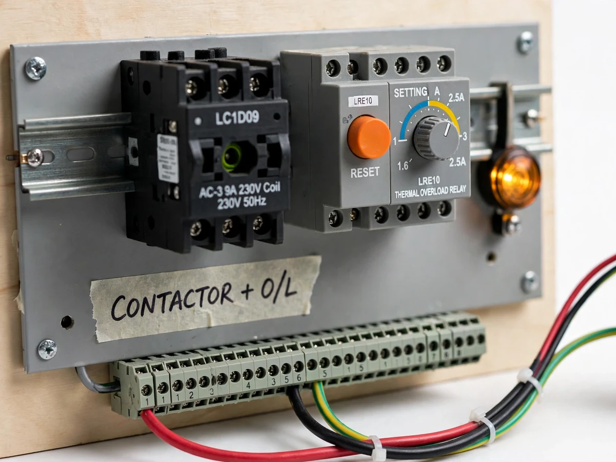
- Power flows through the contactor's main contacts to the motor terminals; the contactor coil is driven by the control circuit.
- Pressing the green start button energizes the contactor coil through the normally-closed stop button, overload relay contact and (latched) e-stop; an auxiliary contact seals the coil in.
- The motor runs direct-on-line; the thermal overload relay's heater elements carry the motor current and its bimetallic strips model the motor's heating.
- On sustained overcurrent the overload relay's NC contact opens, dropping the contactor and lighting the trip lamp — the contactor stays out until the relay is manually reset.
- If the supply fails, the contactor coil de-energizes and the seal-in breaks; when supply returns the motor cannot restart until start is pressed (no-volt release).
- Pressing stop or the e-stop at any time drops the contactor immediately.
Tech stack:
- Single-phase power contactor with auxiliary contacts
- Thermal overload relay (adjustable setting range)
- MCB for short-circuit protection and isolation
- Start/stop pushbutton station + latching emergency stop
- Pilot indicator lamps (supply, run, trip)
- DIN-rail/panel enclosure with terminal blocks
- Single-phase induction motor demo load
| Parameter | Value |
|---|---|
| Supply | 230 V AC single-phase |
| Starting method | Direct-on-line (DOL) through power contactor |
| Overload protection | Thermal (bimetallic) overload relay, adjustable setting — sized to the demo motor; trip class per relay datasheet |
| Short-circuit protection | MCB upstream, rating matched to demo circuit |
| Control | Start/stop pushbuttons with seal-in auxiliary; latching e-stop |
| No-volt release | Contactor drops on supply failure; manual restart required |
| Indication | Pilot lamps: supply healthy, motor running, overload tripped |
| Demo motor | Single-phase induction motor (fractional HP class; exact rating in build notes) |
Project features
- [DOL starting with contactor] The motor is switched through a proper power contactor, not a toggle switch — demonstrating the standard motor-control building block.
- [Thermal overload relay] A bimetallic overload relay with adjustable current setting trips the contactor on sustained overcurrent, protecting the motor against overload and single-phasing effects; its trip class and setting procedure are documented.
- [No-volt release behavior] The start/stop control circuit is wired so the contactor drops out on supply failure and cannot restart until start is pressed again — the required no-volt protection, demonstrated live.
- [MCB short-circuit protection] An MCB upstream of the contactor provides short-circuit and isolation protection with the correct breaking capacity for the demo supply.
- [Start/stop pushbutton station] Green start, red stop and a latching emergency-stop mushroom give the standard operator interface.
- [Status indication] Pilot lamps show supply healthy, motor running and overload tripped states for a readable demo.
- [Fault simulation for demo] The test procedure includes a safe simulated-overload method so the examiner can watch the overload relay trip and the panel lock out.
What is included
- Working motor starter panel (contactor, overload relay, MCB, pushbuttons, e-stop, lamps, enclosure, demo motor)
- Complete wiring diagrams (power circuit and control circuit) with wire sizing notes
- Component list with ratings
- Protection test procedure (buyer-run: verify overload trip, no-volt release and e-stop function)
- Project report PDF (motor starting theory, DOL vs reduced-voltage starting, protection, methodology)
- PPT presentation for final review
- Viva Q&A preparation document (DOL starting current, thermal overload principle, no-volt vs no-load release, trip class)
- Setup and demonstration guide
Limitations & prerequisites
- This is an academic demonstration panel at fractional-HP demo scale; it must not be installed on real plant or building wiring without a licensed electrician's review.
- Overload relay settings are design-selected for the demo motor and verified by the buyer's own test procedure — the panel ships with the setting procedure, not a pre-certified trip curve.
- DOL starting draws high inrush current by principle; reduced-voltage starting (autotransformer/soft starter) is noted as an extension, not included.
- The thermal overload models heating approximately; it does not replace motor winding-temperature sensing.
- Repeated rapid start/stop cycling can nuisance-trip the thermal element — this behavior is documented as a teaching point.
Frequently Asked Questions
Why use a contactor instead of a simple switch?
A contactor gives remote/electrical control, enables the seal-in start/stop logic, allows the overload relay to break the circuit, and provides the no-volt release behavior — none of which a plain switch offers.
How does the thermal overload relay work?
Heater elements in series with the motor current warm bimetallic strips that bend and open a trip contact on sustained overcurrent, mimicking the motor's own thermal behavior. The current setting is adjustable to the motor's rated current.
What is no-volt release?
After a supply failure the contactor drops out and the seal-in breaks, so the motor cannot restart unexpectedly when power returns — the operator must press start again. The demo proves this live.
How is the overload trip demonstrated?
The test procedure includes a safe simulated-overload method so the examiner can watch the relay trip, the contactor drop and the trip lamp light, followed by manual reset.
What are the main limitations?
Demo-scale panel; settings verified by your own tests; DOL inrush is inherent; thermal modeling is approximate, not winding-temperature sensing.
Is this project suitable for a final-year project?
Yes — for Electrical programs. DOL starting, protection coordination basics and real switchgear wiring practice are directly industry-relevant viva material. Suitable for B.E./B.Tech final-year projects in Electrical engineering.
Components & software requirements
- Single-phase power contactor with auxiliary contacts
- Thermal overload relay (adjustable setting range)
- MCB for short-circuit protection and isolation
- Start/stop pushbutton station + latching emergency stop
- Pilot indicator lamps (supply, run, trip)
- DIN-rail/panel enclosure with terminal blocks
- Single-phase induction motor demo load
Delivery information
Built-to-order project. Delivery timeline is shared after order confirmation based on current queue.
Support terms
Complete documentation, setup guide, and viva preparation included. Support for setup and explanation provided.