
More project photos (2)
The problem
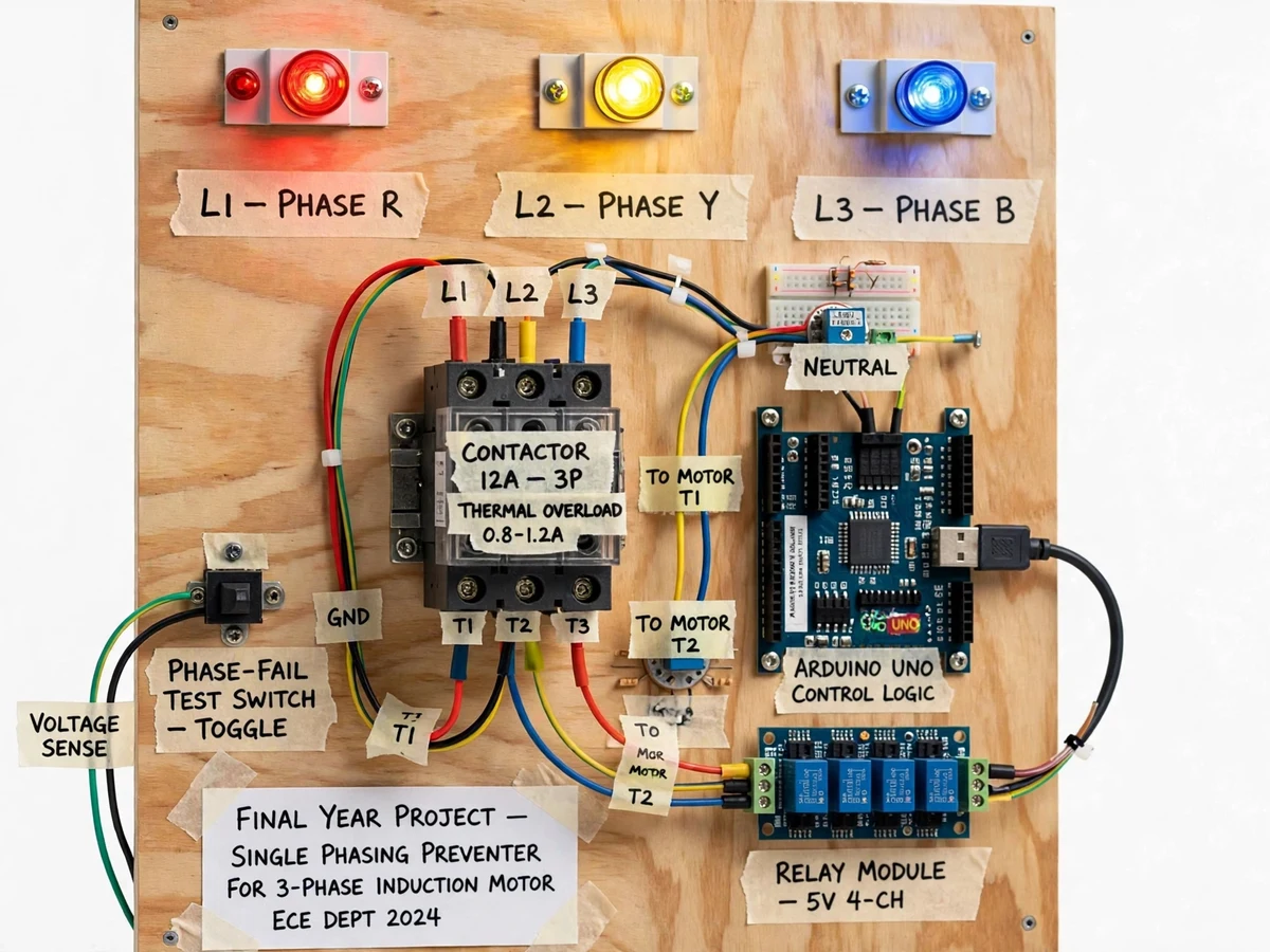
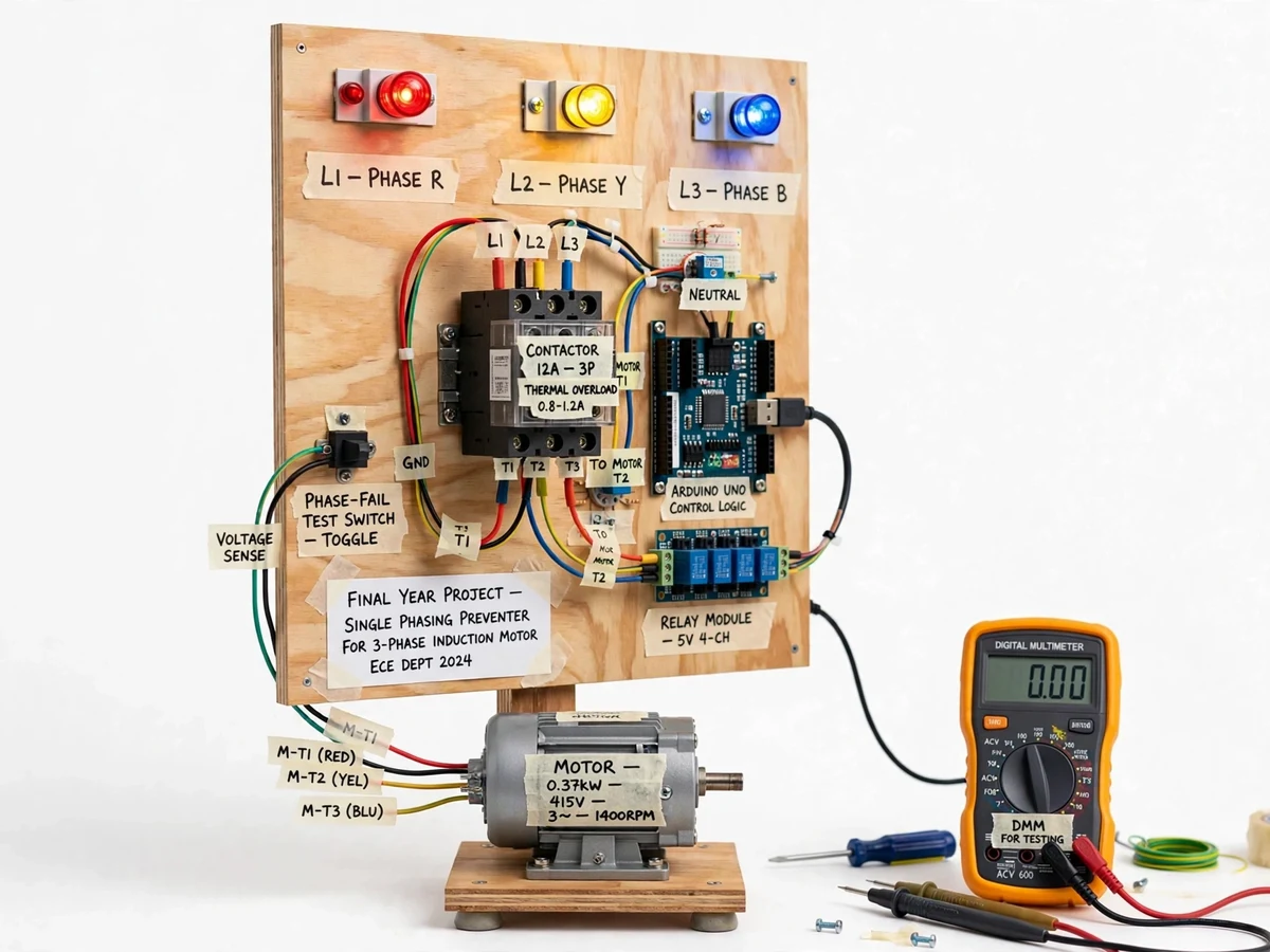
Losing one phase of a 3-phase supply is one of the commonest ways small motors die: the motor keeps running on two phases, draws heavy unbalanced current, and burns out its windings — often with no visible warning until it is too late. A single-phasing preventer watches all three phases and disconnects the motor the instant one disappears. This project builds that protector as a bench panel: three phase-sensing inputs feed an Arduino Uno, red-yellow-blue phase lamps show each phase's health, and on any phase failure the controller drops the 3-pole contactor feeding a 0.37 kW test motor. A phase-fail test toggle lets the student simulate the fault safely and watch the trip happen, and a thermal overload relay adds the second classic layer of motor protection. The report explains the negative-sequence heating mechanism — the real reason single phasing kills motors.
How it works
- With all three phases healthy, the phase lamps glow and the controller holds the contactor closed; the motor runs normally.
- The Arduino samples the three phase-sense inputs every mains cycle.
- If any phase input goes dead — real fault or the test toggle — the logic flags single phasing.
- The controller immediately de-energises the contactor coil, opening all three motor phases.
- The failed phase's lamp goes dark and the trip state latches until reset.
- Restoring the phase and pressing reset re-closes the contactor for the next demonstration run.
Tech stack:
- Arduino Uno control logic
- 3-phase sensing inputs (isolated)
- 12 A 3-pole contactor
- Thermal overload relay 0.8–1.2 A
- 4-channel 5 V relay module
- R/Y/B phase indicator lamps
- Phase-fail test toggle switch
- 0.37 kW 3-phase test motor
| Parameter | Value |
|---|---|
| Test motor | 0.37 kW, 3-phase, 415 V, 1400 rpm (nameplate value) |
| Contactor | 12 A, 3-pole (nameplate value) |
| Overload relay | 0.8–1.2 A thermal, Class 10 type (nameplate value) |
| Trip action | Contactor drop on any single-phase loss (design target: within milliseconds) |
| Indication | R/Y/B phase lamps + trip latch state |
| Test input | Phase-fail simulation toggle |
| Control supply | 5 V logic via relay module isolation |
| Panel | Bench demonstration panel (expected) |
Project features
- [Three-phase sensing] All three phases are monitored continuously through isolated sensing inputs to the Arduino.
- [Millisecond trip action] On phase loss the controller de-energises the contactor coil promptly, disconnecting the motor before damaging currents persist.
- [Phase health lamps] Red, yellow and blue lamps show each phase's presence at a glance across the demonstration room.
- [Phase-fail test toggle] A dedicated toggle simulates losing a phase safely, so the trip can be demonstrated on demand.
- [3-pole contactor output] A 12 A 3-pole contactor switches the motor supply under controller command.
- [Thermal overload relay] A 0.8–1.2 A overload relay adds running overcurrent protection in series with the electronic trip.
- [Relay-module interface] A 4-channel 5 V relay module isolates the Arduino logic from the contactor coil circuit.
What is included
- Fully wired single-phasing preventer panel with test motor
- Arduino with programmed protection firmware
- Wiring diagram and phase-sensing notes
- Fault-simulation and demonstration procedure
- Project report PDF (background, single-phasing theory, negative-sequence heating, protection coordination, test procedure)
- PPT presentation for final review
- Viva Q&A preparation document (single phasing, contactors, overload relays, protection philosophy)
Limitations & prerequisites
- This is a demonstration protector for the bench motor; it is not a certified industrial protection relay and must not be presented as one.
- Trip timing is a design target of the firmware; it is not a calibrated protection curve.
- The unit protects against phase loss and adds overload backup — it does not cover earth faults, short circuits or undervoltage beyond phase absence.
- Demonstration needs a 3-phase supply with a safe way to interrupt one phase; the test toggle provides this.
- Phase sensing is designed for 50 Hz mains; other frequencies are outside the scope.
- Like all protection, it must be demonstrated with the operating procedure's safety steps — mains voltages are present on the panel.
Frequently Asked Questions
Why does losing one phase destroy a motor?
The motor tries to deliver the same power from two phases, so current in the remaining windings rises sharply and negative-sequence currents cause extra rotor heating — the report derives this mechanism.
How does the panel detect the lost phase?
Each phase feeds an isolated sense input to the Arduino; the firmware checks all three every cycle and trips the contactor the moment any one goes dead.
What is the test toggle for?
It safely simulates a phase failure without touching the mains wiring, so the trip action can be demonstrated repeatedly during a viva.
Why is there also an overload relay?
Defence in depth: the electronic trip handles phase loss fast, while the thermal overload relay covers sustained overcurrent from mechanical overload — the two classic motor protections side by side.
How fast does it trip?
The design target is contactor drop within milliseconds of detection — fast enough that the motor never rides through on two phases.
Is this project suitable for a final-year project?
Yes — for Electrical Engineering. Motor protection theory, sensing, control logic and a live fault demonstration in one panel. Suitable for B.E./B.Tech final-year projects in Electrical Engineering.
Components & software requirements
- Arduino Uno control logic
- 3-phase sensing inputs (isolated)
- 12 A 3-pole contactor
- Thermal overload relay 0.8–1.2 A
- 4-channel 5 V relay module
- R/Y/B phase indicator lamps
- Phase-fail test toggle switch
- 0.37 kW 3-phase test motor
Delivery information
Built-to-order project. Delivery timeline is shared after order confirmation based on current queue.
Support terms
Complete documentation, setup guide, and viva preparation included. Support for setup and explanation provided.