
More project photos (2)
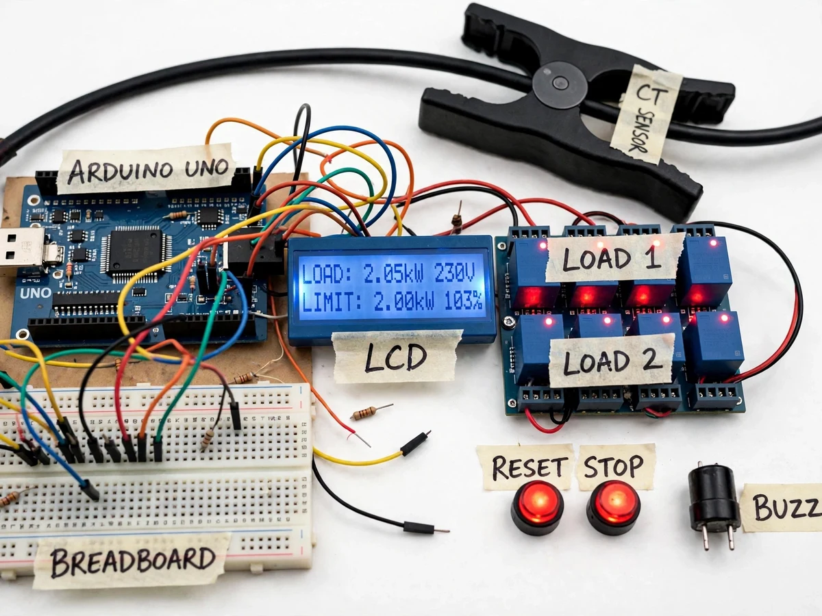
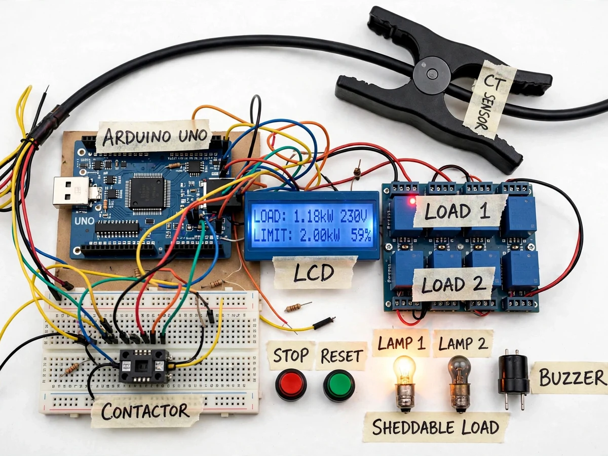
The problem
Commercial and industrial electricity consumers in India are billed not only for energy (kWh) but also for maximum demand — the highest average load recorded over a billing-period integration window. When a facility's recorded demand exceeds its sanctioned contract demand, utilities levy demand penalties, and repeated violations can trigger contractual and equipment-stress consequences. The usual control is entirely manual: someone watches an energy meter and asks staff to switch things off when usage climbs — a method that fails during shift changes, unattended hours, or rapid load ramps. This project automates that supervision with a panel that clamps a split-core CT over the incoming phase, computes live demand with a microcontroller, sounds an alarm as demand approaches the sanctioned limit, and automatically sheds pre-configured non-critical loads before the limit is crossed. The logic mirrors how real industrial demand controllers behave: warning first, load shedding second, and full manual override always available. It gives students hands-on exposure to current sensing, demand computation, relay/contactor switching, and the demand side of energy management.
The incoming phase conductor whose current the CT clamp monitors.
Follow the working sequence
How it works
- The split-core CT clamps around the incoming phase conductor and produces a low-voltage AC signal proportional to load current, which a burden resistor converts to a measurable voltage.
- The Arduino samples the CT signal at several hundred samples per second, computes true RMS current, and multiplies by the supply voltage (with an optional configurable power factor) to get instantaneous kW/kVA.
- Every second the controller folds the latest readings into a sliding integration window, producing the running demand figure that the LCD displays against the stored sanctioned limit.
- When running demand crosses the pre-alarm threshold (default approximately 90% of the limit, configurable), the buzzer sounds and the amber warning LED lights.
- If demand keeps rising past the shed threshold, the controller energizes relay outputs that drop the contactors of pre-configured sheddable (non-critical) loads, starting with the lowest-priority load first.
- Loads restore automatically once demand falls below the restore band, preventing contactor chattering; the full sequence is logged as shed events shown on the LCD.
- Operators can change the limit, thresholds and shed order from the button/keypad menu, and force manual override at any time for testing or maintenance.
Tech stack:
- Arduino Uno (ATmega328P)
- Split-core current transformer (SCT-013 style)
- 16x2 LCD with I2C interface
- 4-channel relay module with 230 V contactors
- Buzzer + panel indicator LEDs
- Push buttons (configuration menu)
- Embedded C (Arduino framework)
- Regulated 5 V/12 V DC power supply
| Parameter | Value |
|---|---|
| Controller | Arduino Uno (ATmega328P, 16 MHz) — datasheet value |
| Current sensing | Split-core CT, 0–100 A primary (SCT-013 style), burden resistor 33 Ω — datasheet value |
| Demand computation | RMS current sampled at several hundred samples/s; kW = V × I × PF |
| Integration window | Configurable, default 1 min (design target); utility windows are 15/30 min — stated for education |
| Settable limit | 0.5–10 kW via keypad (design target, demo range) |
| Alarm thresholds | Pre-alarm default ≈90% of limit; shed threshold ≈98% of limit (configurable) |
| Load-shed outputs | 4 relay channels driving 230 V AC contactors up to 16 A per channel (datasheet value) |
| Display | 16x2 character LCD, live demand vs limit + event messages |
| Settings storage | On-chip EEPROM, retained without power |
| Control power | 12 V DC adapter with 5 V regulation for logic (prototype supply) |
| Restore behaviour | Automatic restore with approximately 5% hysteresis band (design target) |
Project features
- [CT-based load current sensing] A split-core current transformer clamps over the supply phase without cutting the cable, giving the controller a safe, isolated measurement of load current for demand computation.
- [Live demand computation] The microcontroller samples current continuously and computes running demand in kW/kVA over a configurable integration window, exactly how utilities evaluate maximum demand.
- [Two-stage peak-load alarm] A configurable pre-alarm threshold (e.g. 90% of limit) triggers the buzzer and warning LED before the limit is reached; a second stage fires if demand is still rising toward the limit.
- [Automatic sheddable-load output] Pre-configured non-critical loads switch off through relay-driven contactors when demand approaches the sanctioned limit, and restore automatically (with hysteresis) once demand settles back down.
- [16x2 LCD demand display] Live demand, set limit, and percentage-of-limit are shown continuously, with plain-text alarm and shed-status messages during events.
- [Limit configuration] The sanctioned demand limit and alarm thresholds are set from the push-button menu and stored in EEPROM, so settings survive power cycles.
- [Manual override] A dedicated button set holds automatic shedding OFF for maintenance or demonstrations, with the override state clearly indicated on the LCD.
What is included
- Working maximum-demand-limiter panel with CT clamp, Arduino, LCD, relays, contactors, buzzer and buttons
- Complete firmware source code with comments (Arduino/embedded C)
- Circuit and wiring diagrams with CT burden-resistor calculations
- Component list with part numbers and ratings
- Keypad configuration and calibration procedure document
- Project report PDF (background, demand-charging context, methodology, working, results)
- PPT presentation for final review
- Viva Q&A preparation document (CTs, RMS measurement, demand windows, relay/contactor driving, hysteresis)
Limitations & prerequisites
- The prototype computes demand from a single-phase CT on a 230 V demo supply; a real three-phase industrial installation needs three CTs and phase-sequence handling, which is documented as an extension path.
- Power factor is entered as a configurable constant; without a real power-factor measurement circuit, kW figures are approximate and must be verified with a calibrated reference meter during calibration.
- Contactor switching is limited to the relay-module ratings (230 V AC, 16 A per channel) — actual industrial loads need appropriately rated industrial contactors and panel wiring, which the design notes specify but the demo panel does not include.
- This is an academic demonstration panel, not a BIS/IEC-certified industrial demand controller; it must not be installed on a live industrial feeder without qualified review and proper protection devices.
- Load restoration follows a fixed priority order; priority-based shedding schemes with dynamic priorities would need firmware extension.
Frequently Asked Questions
Which controller is used?
An Arduino Uno (ATmega328P) reads the CT sensor through an analog input, computes RMS current and running demand, drives the LCD, buzzer and relay outputs, and stores the sanctioned limit in EEPROM. The choice keeps the build affordable, well-documented for students, and fast enough for per-second demand updates.
How does the CT sensor measure current safely?
The split-core CT clamps around the insulated phase conductor without cutting it. Magnetic coupling produces a small secondary current proportional to load current, which a burden resistor converts to a voltage the microcontroller's ADC can read. The CT output stays at low voltage, so the sensing side is galvanically isolated from the mains.
What loads get shed, and can the order change?
Four relay channels switch contactor-driven loads marked as sheddable — non-critical loads such as decorative lighting or air-conditioning zones. The shed order is configured through the push-button menu from lowest to highest priority, and the firmware restores loads automatically with a hysteresis band once demand settles.
What power supply does the panel need?
The control electronics run on a 12 V DC adapter with on-board 5 V regulation for the logic circuits. The demo loads are standard 230 V AC lamps/appliances through the relay channels; the CT clamp itself needs no power. Field deployment on an industrial feeder would need a proper panel supply and protection devices.
Can this be extended to three-phase?
Yes — the firmware structure supports it, but the base build ships single-phase. A three-phase extension needs two additional CTs, voltage sensing on each phase, and per-phase demand aggregation; this is documented in the report's future-scope section and can be developed as a customization.
Is this project suitable for a final-year project?
Yes — for Electrical, E&TC and Instrumentation programs. It demonstrates current-transformer sensing, RMS measurement, embedded firmware, demand computation the way utilities bill it, and relay/contactor power control — a strong mix of measurement, control and energy-management topics for the viva.
Components & software requirements
- Arduino Uno (ATmega328P)
- Split-core current transformer (SCT-013 style)
- 16x2 LCD with I2C interface
- 4-channel relay module with 230 V contactors
- Buzzer + panel indicator LEDs
- Push buttons (configuration menu)
- Embedded C (Arduino framework)
- Regulated 5 V/12 V DC power supply
Delivery information
Built-to-order project. Delivery timeline is shared after order confirmation based on current queue.
Support terms
Complete documentation, setup guide, and viva preparation included. Support for setup and explanation provided.
Download free synopsis (PDF)
Enter your name and email — the synopsis PDF downloads immediately. We may send occasional project updates; no spam, unsubscribe anytime.