
More project photos (2)
The problem
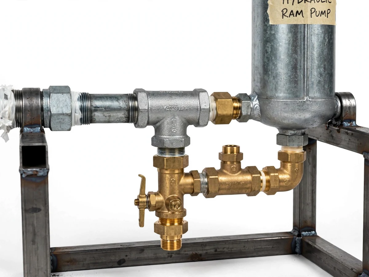
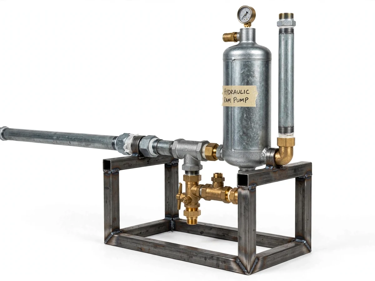
Across farms and hillside homes, a stream or spring often flows just a few metres below the field or house that needs water. Lifting that water normally means an electric or diesel pump — which assumes grid power or fuel money, both unreliable or costly off-grid. Commercial hydraulic ram pumps solve this elegantly but are imported or priced beyond a student or small farmer's reach. Students meet the ram pump's core phenomenon — water hammer — only as a textbook warning about bursting pipes, never as something useful. This project reframes it: a working ram pump built entirely from standard GI pipe fittings, brass valves and a fabricated air chamber on a welded MS stand. Fed by a continuous flow with a modest supply head, it pumps a fraction of the inflow to a delivery head many times higher, demonstrating fluid transients, valve timing and honest engineering trade-offs in one working model.
Water flows downhill through the drive pipe, building momentum in the moving column.
Follow the working sequence
How it works
- Water from a supply tank or stream flows downhill through the drive pipe, gaining velocity; the straight, rigid drive run is sized so the moving water column carries substantial momentum.
- The moving water escapes freely through the open waste valve, accelerating until the drag on the valve overcomes its weight — then the waste valve slams shut almost instantly.
- The sudden stop converts the column's kinetic energy into a sharp water-hammer pressure spike, whose peak can reach several times the static supply pressure (expected, site-dependent).
- The pressure spike forces open the one-way delivery valve; a slug of water is driven past it into the air chamber while the waste valve stays closed.
- As drive-line pressure decays, the delivery valve snaps shut (preventing backflow) and the falling pressure lets the waste valve drop open again, restarting the cycle automatically at roughly 30–60 strokes per minute (expected).
- Compressed air trapped in the air chamber expands during the low-pressure phase, squeezing water steadily up the delivery pipe — smoothing the pulsing flow into near-continuous delivery toward the overhead tank.
- The overhead tank receives water at a head typically 5–10 times the supply head (design target, site-dependent); the remaining inflow (about 85–90%) discharges from the waste valve and is returned to the stream or collected for other use.
Tech stack:
- Galvanized iron (GI) pipe fittings
- Brass check valves · waste valve assembly
- Steel air chamber (pressure vessel)
- MS square-tube welded stand
- Bourdon pressure gauge
- PTFE thread-seal tape · pipe sealant
- Pipe wrenches · threading kit
- Overhead tank (demonstration load)
| Parameter | Value |
|---|---|
| Supply head required | Minimum ~1 m (design value, site-dependent) |
| Delivery head | Typically 5–10x the supply head (design target, site-dependent) |
| Drive pipe | Approximately 1 in diameter, 3–6 m long (design values) |
| Delivered flow | Approximately 10–15% of inflow (expected); ~85–90% discharged by the waste valve |
| Cycle rate | Approximately 30–60 strokes per minute (expected) |
| Energy conversion efficiency | Typically 60–80% D'Aubisson efficiency (expected, site-dependent) |
| Fitting pressure rating | Approximately 10 bar for standard GI fittings (datasheet); sets the pressure ceiling |
| Prototype footprint | Approximately 1.2 m × 0.6 m on the MS stand (approximate) |
Project features
- [Automatic water-hammer pumping cycle] Water rushing down the drive pipe accelerates until drag slams the waste valve shut; the sudden stop converts the water column's momentum into a sharp pressure spike that forces the delivery valve open and drives a slug of water into the air chamber. The cycle restarts by itself, roughly 30–60 strokes per minute (expected), with no electricity or fuel.
- [Air chamber flow smoothing] A fabricated cylindrical steel pressure vessel traps compressed air above the pumped water; the air cushion absorbs the hammer pulses and pushes water steadily up the delivery pipe, converting intermittent surges into near-continuous flow to the overhead tank.
- [Tunable waste valve] The waste valve's stroke length and closing weight are adjustable, so the cycle rate and delivered flow can be tuned to the site's actual supply head and flow during commissioning.
- [Momentum-designed drive pipe] The drive line is sized at approximately 1 inch diameter and 3–6 m long (design values) — a straight, rigid run that gives the moving water column enough momentum to generate a useful pressure spike.
- [Overhead-tank delivery demonstration] The delivery pipe carries pumped water to a tank at a head typically 5–10 times the supply head (design target, site-dependent), making the lift visible and measurable for the demonstration.
- [All-plumbing-fittings construction] Every component is a standard GI tee, elbow, union or brass valve — deliberately chosen so the pump can be repaired with a local plumber's parts, a genuine maintainability decision for rural use.
- [Pressure-gauge monitoring] A bourdon pressure gauge on the air chamber shows the hammer pulses and the steady delivery pressure, used both for tuning the valves and for explaining the cycle in the viva.
What is included
- Assembled and tuned hydraulic ram pump prototype on an MS stand
- Bill of materials with exact fitting sizes and quantities
- Pipe layout and assembly drawing
- Water-hammer calculation notes explaining the pressure spike
- Waste-valve tuning guide with a pressure-reading procedure
- Project report PDF (background, theory, methodology, calculations, test procedure)
- PPT presentation for final review
- Viva Q&A preparation document (water hammer, valve timing, efficiency, site constraints)
Limitations & prerequisites
- Requires a continuous flowing water source with at least ~1 m of supply head — the pump cannot work at flat or dry sites, or from a still tank without head.
- Only ~10–15% of the inflow is delivered; roughly 85–90% of the water discharges through the waste valve, so the source must have plentiful flow and the waste water must be returned or reused.
- The waste valve clatters loudly on every stroke — around 30–60 times a minute (expected) — making indoor or quiet-environment demonstrations impractical.
- Delivered flow is a trickle suited to filling a tank over time; it cannot irrigate a field directly or supply peak-demand outlets.
- Lift ratio and efficiency are site- and tuning-dependent — the 5–10x head and 60–80% efficiency figures are typical ranges and design targets, not guaranteed measured values.
- Delivery head is capped by the pressure rating of standard plumbing fittings (~10 bar for GI, datasheet), so very high single-stage lifts are out of scope.
- The air chamber slowly loses its air cushion as air dissolves into the water; it needs periodic re-charging by draining and restarting the pump.
Frequently Asked Questions
How does a hydraulic ram pump lift water without electricity or fuel?
Water flowing down the drive pipe gains momentum and slams the waste valve shut; the sudden stop creates a water-hammer pressure spike that forces the delivery valve open, pushing a slug of water into the air chamber. The cycle repeats automatically, and the air chamber smooths the pulses into steady delivery to the overhead tank.
Is this project suitable for a final-year project?
Yes — for Mechanical, Civil and Agricultural engineering programs. It demonstrates unsteady-flow fluid mechanics (the water-hammer effect), valve design and timing, pressure-vessel fabrication, pipe fitting and workshop skills, all in a single working prototype with a clearly measurable output.
What does the pump need to run during a demonstration?
A continuous water source with at least ~1 m of supply head above the pump, a straight drive pipe run of about 3–6 m (design value), and an overhead tank or raised outlet for the delivery pipe. Waste water from the waste valve is collected or returned to the source.
How much water does it actually deliver?
Roughly 10–15% of the inflow (expected); about 85–90% discharges through the waste valve. The delivered fraction is a design trade-off — higher lift means less delivered flow. The pump is meant to trickle-fill a tank over hours, not to irrigate a field directly.
Can the pump be customized?
Realistic options include larger pipe sizes for more flow, a snifter (air-inlet) valve to auto-replenish the air chamber, longer delivery runs to distant tanks, and a second pump in series for higher heads. Each option is quoted separately after a feasibility check.
What are the main limitations?
It needs a flowing source with minimum head, wastes most of the inflow, is noisy, and delivers only a small fraction of water to the tank. Site geometry and valve tuning decide real performance — the headline figures are design targets, not guarantees. The full list sits under Limitations & Prerequisites.
Components & software requirements
- Galvanized iron (GI) pipe fittings
- Brass check valves · waste valve assembly
- Steel air chamber (pressure vessel)
- MS square-tube welded stand
- Bourdon pressure gauge
- PTFE thread-seal tape · pipe sealant
- Pipe wrenches · threading kit
- Overhead tank (demonstration load)
Delivery information
Built-to-order project. Delivery timeline is shared after order confirmation based on current queue.
Support terms
Complete documentation, setup guide, and viva preparation included. Support for setup and explanation provided.
Download free synopsis (PDF)
Enter your name and email — the synopsis PDF downloads immediately. We may send occasional project updates; no spam, unsubscribe anytime.