
More project photos (2)
The problem
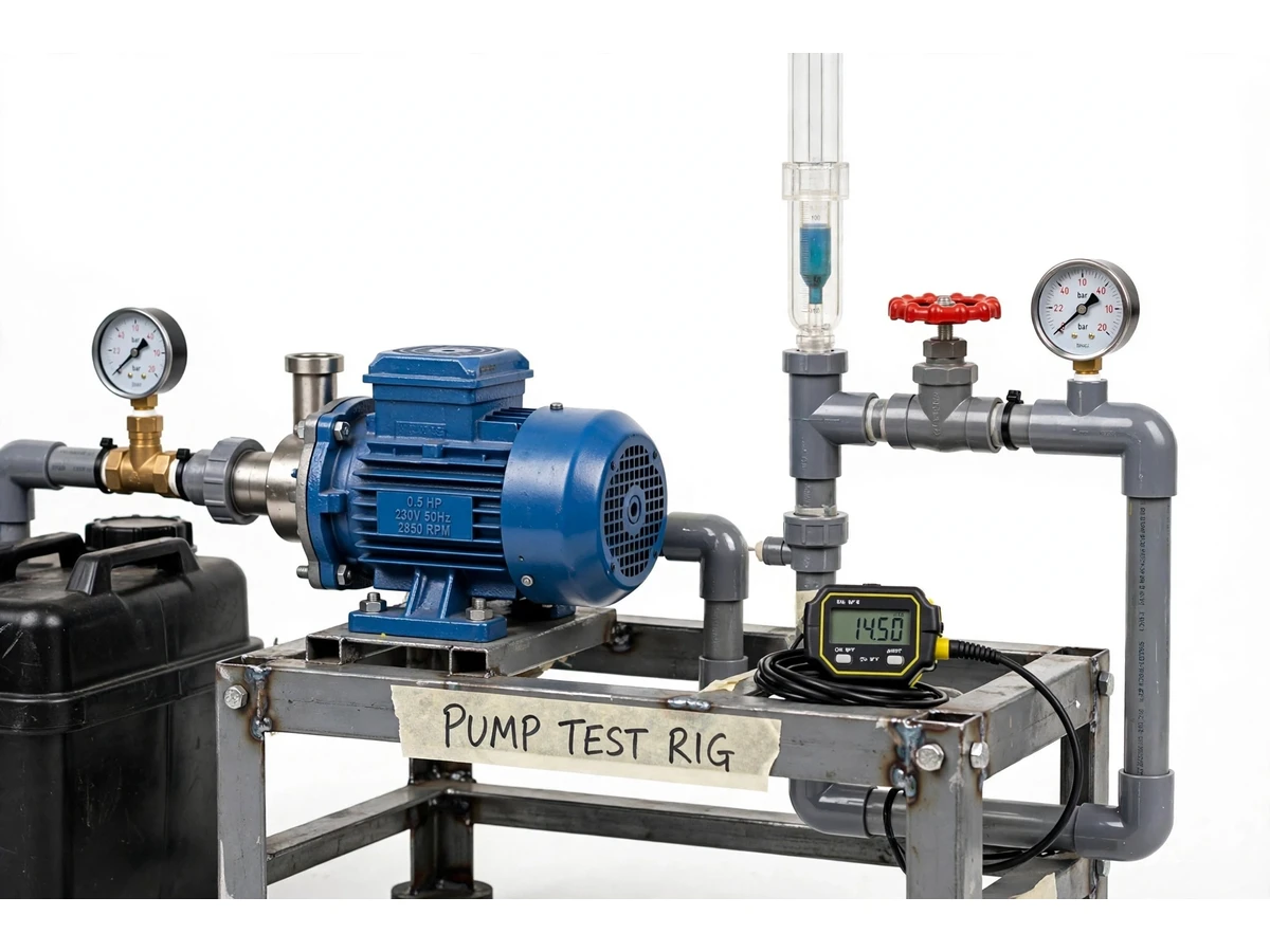
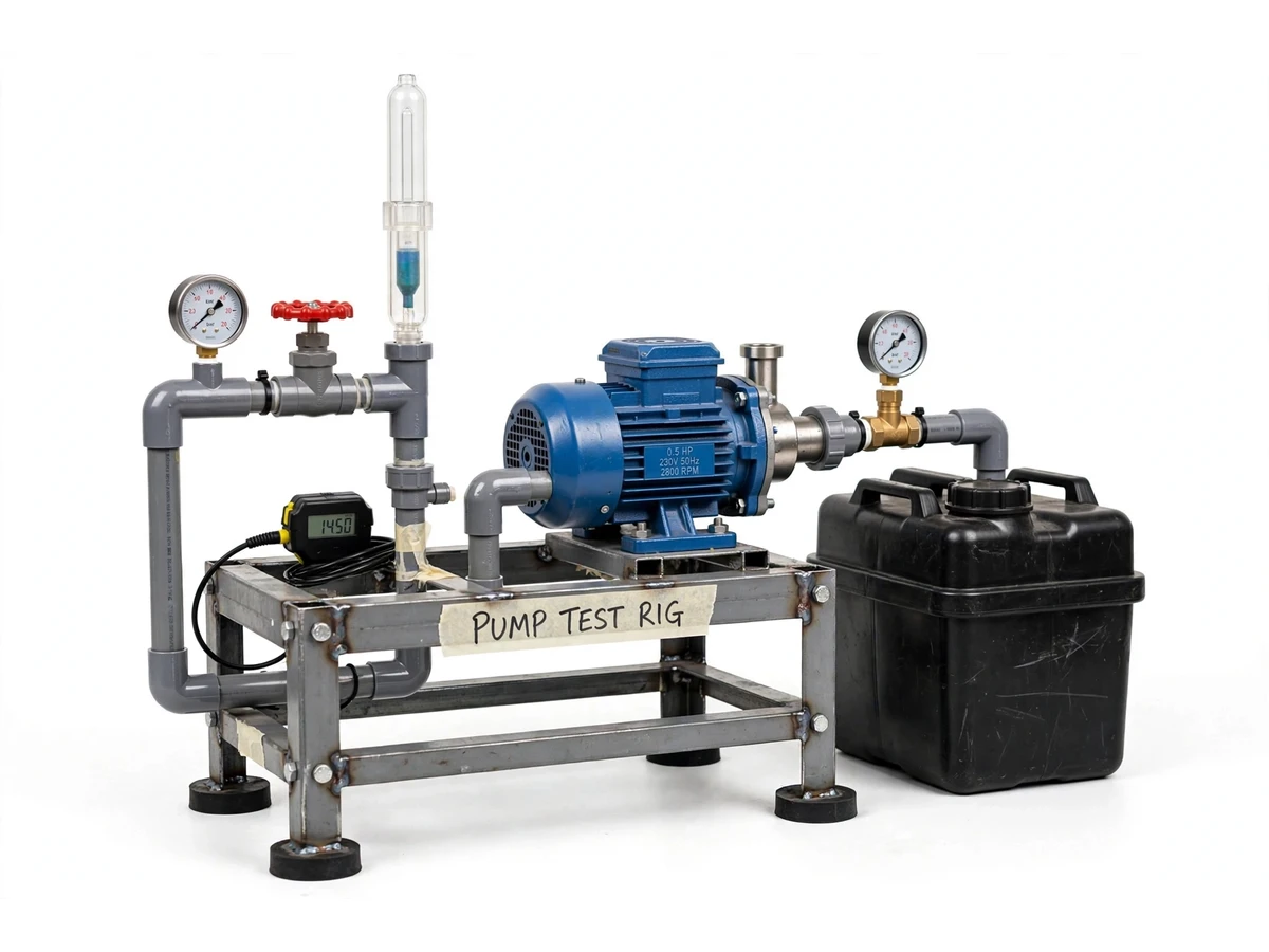
Fluid mechanics students study the centrifugal pump characteristic curves — head vs discharge, power vs discharge, efficiency vs discharge — in every textbook, but many college labs lack a working rig, so the curves remain theory on a page. This project fabricates a complete, bench-scale centrifugal pump test rig: a monoblock pump on a welded MS frame, a closed-loop sump circuit, suction and delivery Bourdon gauges, a delivery gate valve for throttling, a rotameter with a volumetric tank cross-check, a non-contact tachometer and an energy meter on the motor supply. The student runs the full experiment — priming, throttled operating points, steady-state readings — and computes total head, hydraulic power and efficiency from their own gauge and meter data, plotting the three characteristic curves and identifying the best-efficiency point. Because every number in the report comes from the student's own test run, the viva discussion is grounded in real procedure and real data.
How it works
- Fill the sump tank and prime the pump by flooding the casing and suction line with water to expel trapped air.
- Open the delivery valve fully, start the pump, and once flow is steady record suction and delivery gauge readings, rotameter reading, motor RPM and the energy-meter count.
- Throttle the delivery valve in steps toward shut-off; at each position wait for steady flow and record the full instrument set.
- Compute total head at each point from the gauge difference plus the gauge-centre elevation difference.
- Compute discharge from the rotameter (cross-checked with a timed fill of the volumetric tank) and hydraulic power as ρ·g·Q·H.
- Compute input power from the energy meter over a timed interval, then efficiency = hydraulic power ÷ input power at each operating point.
- Plot the H–Q, P–Q and η–Q curves, locate the best-efficiency point from your own data, and compare against the manufacturer's rated duty.
Tech stack:
- 0.5 HP single-phase monoblock centrifugal pump
- Welded MS-angle frame with anti-vibration mounts
- Bourdon pressure gauges (suction + delivery)
- Gate valve for delivery throttling
- Rotameter + volumetric measuring tank
- Non-contact digital tachometer + energy meter
- GI/PVC piping, foot valve and strainer
- Closed-loop HDPE sump tank
| Parameter | Value |
|---|---|
| Pump rating | 0.5 HP, single phase, ~2800 RPM (manufacturer nameplate) |
| Rated duty | Approximately 25–30 L/min at 8–10 m head (design target) |
| Expected operating window | Approximately 5–35 L/min across valve positions |
| Sump tank | Approximately 60 L HDPE (approximate) |
| Gauge ranges | 0–2.5 bar suction, 0–4 bar delivery (typical) |
| Overall frame size | Approximately 900 × 500 × 700 mm |
| Supply | 230 V single-phase |
| Test quantities | Head, discharge, input power, speed — all student-measured |
Project features
- [0.5 HP monoblock centrifugal pump on welded frame] Single-phase monoblock pump mounted on a rigid MS-angle frame with anti-vibration pads — a compact, lab-safe unit that runs on a standard 230 V outlet.
- [Suction and delivery pressure gauges] Bourdon gauges on both sides of the pump so total head is computed from real pressure readings, not nameplate claims.
- [Throttled operating points] A gate valve on the delivery line lets the student step through shut-off to wide-open flow, capturing the full head–discharge characteristic.
- [Dual flow measurement] A rotameter on the delivery line plus a volumetric collection tank with a level scale, so every flow reading can be cross-checked.
- [Input power measurement] An energy meter on the pump supply records the electrical input at each operating point, making the efficiency calculation honest and complete.
- [Non-contact tachometer] Motor speed is recorded at every operating point, supporting the affinity-law discussion in the report.
- [Closed-loop water circuit] Sump-to-pump-to-tank recirculation with a foot valve and strainer — no continuous water supply needed and no water wasted during the test.
- [Curves from your own readings] The report template computes head, hydraulic power and efficiency from the student's own instrument readings — no pre-filled expected curves anywhere.
What is included
- Fabricated test rig: frame, sump tank, piping, valves and strainer
- 0.5 HP monoblock centrifugal pump
- Suction and delivery pressure gauges
- Rotameter and volumetric measuring tank
- Non-contact tachometer and energy meter
- Step-by-step test procedure manual
- Observation and calculation sheets (blank, for your readings)
- Project report PDF (theory, procedure, sample calculations, curve templates)
- PPT presentation for final review
- Viva Q&A preparation document
Limitations & prerequisites
- The 25–30 L/min rated duty is the pump's nameplate design target; the curve you report is measured on your build and will differ with piping and voltage.
- Gauges are mechanical Bourdon type with approximately ±1.6% full-scale accuracy class — readings near shut-off carry proportionally higher percentage error.
- Efficiency values depend on supply voltage stability; a sagging line voltage during the test shifts the measured input power.
- The rig is designed for clean water only — no slurries, oils or chemical solutions.
- Continuous dry-running overheats the pump; the procedure requires verified priming before every start.
Frequently Asked Questions
What curves does the student actually plot?
Head vs discharge (H–Q), input power vs discharge (P–Q) and efficiency vs discharge (η–Q). All three are computed from the student's own gauge, rotameter and energy-meter readings — the report contains calculation sheets and blank curve templates, not pre-filled data.
How is total head calculated?
From the delivery gauge reading minus the suction gauge reading (converted to metres of water) plus the vertical distance between the two gauge centres. The manual works through one full example with real units.
Why are there two flow-measurement methods?
The rotameter gives instant readings during throttling, while the volumetric tank gives an absolute timed-fill check. Comparing the two is itself a viva-ready error-analysis exercise.
Does the rig need a continuous water supply?
No. It is a closed-loop circuit: water recirculates from the sump tank through the pump and back, so it runs in any indoor lab with a power socket.
What pump theory should the student know for the viva?
Velocity triangles at impeller exit, why head falls as flow rises, shut-off head, the best-efficiency point, cavitation and NPSH, and the affinity laws — all covered in the Q&A document with reference to the student's own curves.
Is this project suitable for a final-year project?
Yes — for Mechanical Engineering. It is the standard fluid-mechanics laboratory experiment, fabricated as a working rig with real instruments, and the report documents an experiment the student genuinely performed. Suitable for B.E./B.Tech final-year projects in Mechanical Engineering.
Components & software requirements
- 0.5 HP single-phase monoblock centrifugal pump
- Welded MS-angle frame with anti-vibration mounts
- Bourdon pressure gauges (suction + delivery)
- Gate valve for delivery throttling
- Rotameter + volumetric measuring tank
- Non-contact digital tachometer + energy meter
- GI/PVC piping, foot valve and strainer
- Closed-loop HDPE sump tank
Delivery information
Built-to-order project. Delivery timeline is shared after order confirmation based on current queue.
Support terms
Complete documentation, setup guide, and viva preparation included. Support for setup and explanation provided.