
More project photos (2)
The problem
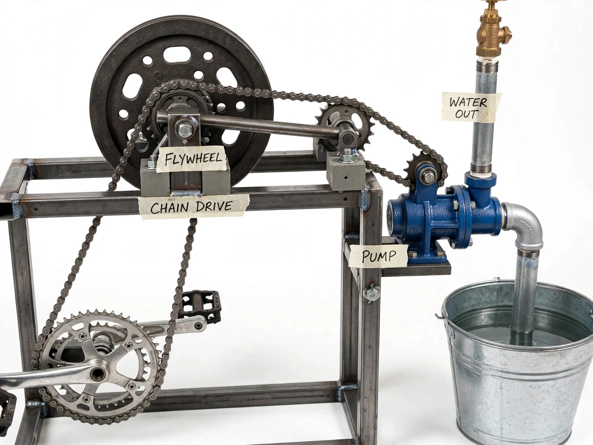
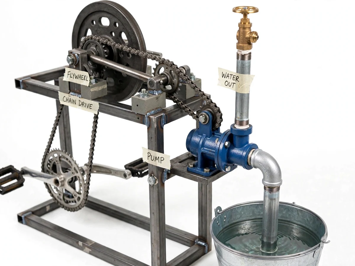
In villages and farms without reliable electricity, lifting water for irrigation still depends on expensive diesel pump sets or on exhausting manual labor. Diesel sets cost money to buy and run, need fuel supply chains, and emit fumes; hand pumps and treadle pumps demand continuous hard effort because the pumping load rises and falls with every stroke. A bicycle-pedal drive is a proven human-power source, but a pump connected straight to the pedals surges and stalls with each pedal stroke, wasting effort and stressing the pump. Adding a flywheel changes this: the heavy disc stores energy during the strong part of the pedal stroke and releases it during the weak part, smoothing the shaft speed so the centrifugal pump works against a steadier load. This project builds that complete machine — pedal crank, chain drive, flywheel, centrifugal pump and piping — as a fabricated, demonstrable prototype. Nothing is simulated: the student assembles the rig, primes the pump, pedals, and measures the actual flow rate against head using the included test procedure.
Pedals the crankset at a comfortable 40-60 rpm.
Follow the working sequence
How it works
- The rider pedals the crankset at a comfortable cadence of approximately 40–60 rpm.
- The crank chainring drives the intermediate shaft through a roller chain at a design ratio of approximately 2:1.
- The cast-iron flywheel on the intermediate shaft absorbs torque during the power stroke and releases it during the dead stroke, smoothing the speed ripple before it reaches the pump.
- A second chain stage steps the smoothed shaft speed up to the pump's design operating range (approximately 1,000–1,400 rpm, design target).
- The primed centrifugal pump draws water from the sump through the suction pipe and foot valve, and the spinning impeller throws it out through the volute into the discharge pipe.
- The gate valve on the discharge sets the operating point; a hand tachometer (test procedure included) reads shaft speed while timed discharge is collected in a calibrated container.
- The student tabulates flow rate against measured head and compares it with the design calculations — the flywheel's effect is demonstrated by repeating a run with the flywheel disengaged.
Tech stack:
- MS steel fabrication · welding
- Bicycle crankset · pedals
- Roller chain · sprockets
- Cast-iron flywheel
- Centrifugal pump (0.5–1 hp class)
- Pillow-block bearings
- Foot valve · gate valve · piping
- CAD fabrication drawings · test procedure
| Parameter | Value |
|---|---|
| Pedal cadence | 40–60 rpm (comfortable, approximate) |
| Stage-1 chain ratio | Approximately 2:1 (design) |
| Flywheel | Cast-iron disc, approx. 300–400 mm diameter, 10–15 kg (design range) |
| Pump | Single-stage centrifugal, 0.5–1 hp class |
| Design pump speed | Approximately 1,000–1,400 rpm (design target) |
| Design head | Approximately 5–8 m total head (design target) |
| Design flow rate | Approximately 10–25 L/min at design head (design target; verified by buyer-run test) |
| Suction lift | Up to approximately 3 m with foot valve (approximate) |
| Frame | Welded MS square-tube with mesh flywheel guard |
| Footprint | Approximately 1.2 m × 0.6 m (approximate) |
Project features
- [Pedal crank drive] A bicycle-style crankset with two pedals drives the input shaft — a familiar, low-cost human-power source that any rider can operate without training.
- [Chain transmission] A roller-chain stage at a design ratio of approximately 2:1 steps the comfortable 40–60 rpm pedal cadence up toward pump speed; chain tension is set with an adjustable tensioner plate.
- [Flywheel energy smoothing] A cast-iron flywheel on the intermediate shaft stores energy on the power stroke and releases it on the dead stroke, keeping pump speed steadier and pedaling noticeably easier — the project's core mechanical concept.
- [Centrifugal pump water lifting] A commercial single-stage centrifugal pump draws water from a sump (tank, well or pond model) through a foot valve and discharges it through piping with a gate valve for flow control.
- [Welded steel frame] A square-tube MS frame carries the crank, pillow-block bearings, flywheel and pump in one rigid, student-fabricated structure with a mesh flywheel guard.
- [Timed-discharge test setup] A calibrated collection container and stopwatch method let the student measure flow rate at a measured discharge head — every performance figure in the report comes from this buyer-run test.
- [Adjustable, maintainable build] Standard bicycle and pump parts, pillow-block bearings and a bolted frame mean the rig can be disassembled, aligned and serviced with basic workshop tools.
What is included
- Working pedal-pump prototype, built to order
- CAD fabrication drawings (frame, shaft layout, drive assembly)
- Chain drive and flywheel sizing calculation sheets
- Pump selection notes and piping layout
- Assembly, alignment and priming guide
- Buyer-run flow-rate test procedure with result tables
- Project report PDF (background, theory, design calculations, test results)
- PPT presentation for final review
- Viva Q&A preparation document (flywheel energy, chain drives, pump characteristics)
Limitations & prerequisites
- Human power bounds the output: a rider sustains roughly 50–100 W, so flow is far below an electric pump set — this is a demonstration and small-scale irrigation rig, not a farm pump replacement.
- Flow rate, head and speed figures are design targets; actual values depend on the pump unit, priming, alignment and the rider, and are established by the buyer's own timed-discharge test.
- The pump must be primed before every run; running dry damages the seal and impeller.
- Suction lift is limited to a few metres — deep borewells need a submersible or jet pump, which this rig does not demonstrate.
- The flywheel is heavy and stores real rotational energy; the mesh guard must be fitted and loose clothing kept clear during operation.
- Prototype finish is workshop-grade (welded steel, standard parts), not a certified agricultural product.
Frequently Asked Questions
Is this project suitable for a final-year project?
Yes — for Mechanical Engineering and Diploma mechanical programs. It is a complete design-build-test cycle: power transmission sizing, flywheel energy storage, centrifugal pump characteristics and workshop fabrication. Students assemble the rig, run the timed-discharge tests and defend real measured results, which is exactly what examiners look for in a final-year project.
How much water will it actually pump?
The design target is approximately 10–25 L/min at 5–8 m head, but this is a target, not a promise. Your actual figures come from the included timed-discharge test on your own build, and they depend on the pump, priming and the rider's pedaling.
What does the flywheel actually do?
Pedaling torque pulses twice per revolution; the flywheel stores energy during the strong part of the stroke and releases it during the weak part, smoothing shaft speed. You can feel and measure the difference by running the rig with the flywheel disengaged — the test procedure includes this comparison.
Does it need electricity or fuel?
No — that is the whole point of the design. It is fully human-powered, so it runs anywhere without a grid connection or fuel supply. That makes it ideal for off-grid irrigation studies, appropriate-technology demonstrations and villages where electricity is unreliable or unavailable.
Can it be customized?
Realistic options include different chain ratios, a reciprocating pump head instead of the centrifugal pump, a larger flywheel, or a solar-assist motor as an optional extension. Any change alters the drive and flywheel sizing, so the calculation sheets are re-done for the order.
What will I receive with the project?
The working prototype rig, CAD fabrication drawings, chain-drive and flywheel sizing calculation sheets, the assembly and priming guide, the buyer-run flow-rate test procedure, the project report PDF, a PPT presentation and a viva Q&A document — everything needed to demonstrate, explain and defend the build. Suitable for B.E./B.Tech final-year projects in Mechanical and Electrical engineering.
Components & software requirements
- MS steel fabrication · welding
- Bicycle crankset · pedals
- Roller chain · sprockets
- Cast-iron flywheel
- Centrifugal pump (0.5–1 hp class)
- Pillow-block bearings
- Foot valve · gate valve · piping
- CAD fabrication drawings · test procedure
Delivery information
Built-to-order project. Delivery timeline is shared after order confirmation based on current queue.
Support terms
Complete documentation, setup guide, and viva preparation included. Support for setup and explanation provided.
Download free synopsis (PDF)
Enter your name and email — the synopsis PDF downloads immediately. We may send occasional project updates; no spam, unsubscribe anytime.