
More project photos (2)
The problem
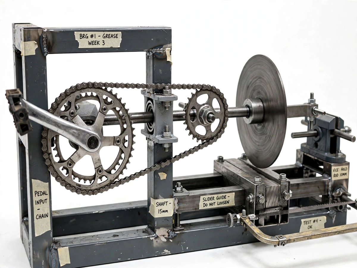
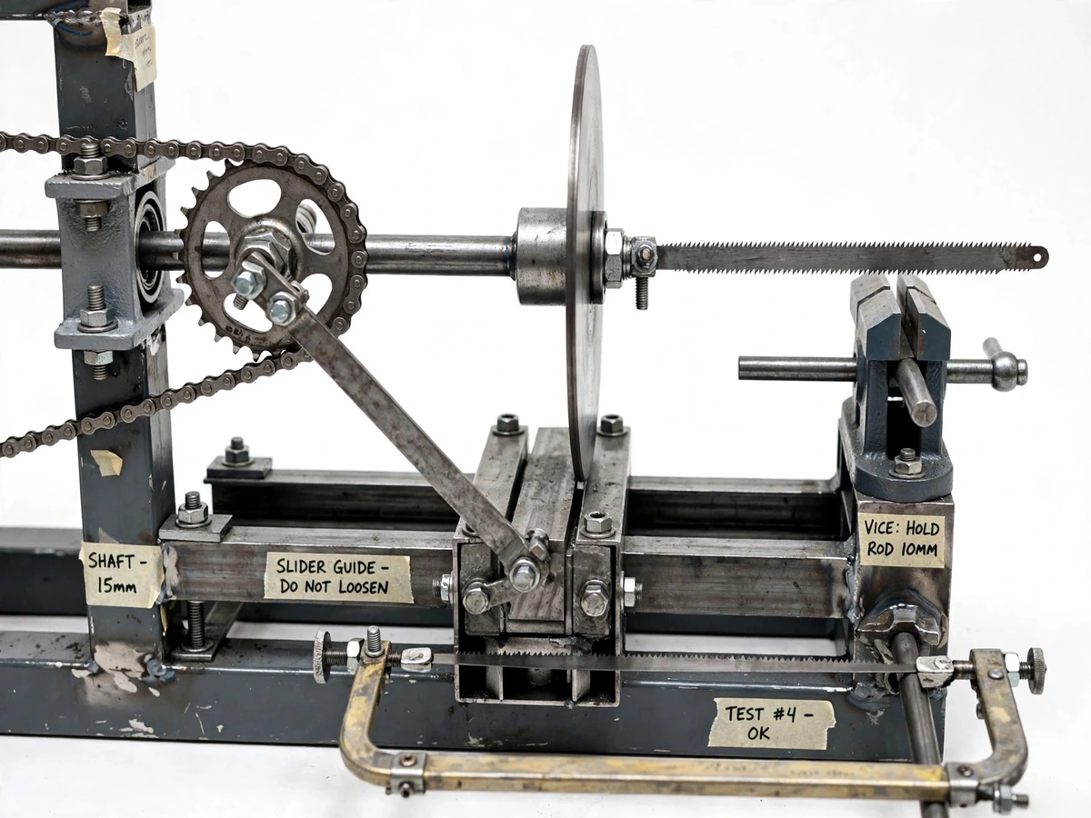
Cutting a metal rod in a small workshop or college fabrication lab is usually done in one of two ways: by hand with a hacksaw, which is slow and tiring, or with an electric power hacksaw, which needs mains supply, costs far more, and cannot run where there is no power. Many student workshops, rural ITIs and off-grid sites still rely entirely on manual sawing. This project solves that gap mechanically rather than electrically: it takes the most familiar human-powered drive available — a bicycle pedal and chain — and converts it into the reciprocating motion a hacksaw needs. A roller chain drives a crank disc carried on pillow-block bearings; a crank pin and connecting rod turn that rotation into linear motion of a slider that carries a standard hacksaw frame; the crank-rocker geometry creates a quick return, so the cutting stroke runs slower than the idle return stroke. A bench vice clamps the workpiece under the blade. There is no motor, no wiring and nothing to plug in — the machine works anywhere an operator can sit and pedal.
Pedals the bicycle crank at a comfortable 50-60 rpm cadence.
Follow the working sequence
How it works
- The operator pedals a standard bicycle crank; the large chainring drives a roller chain connected to the smaller driven sprocket on the lay shaft.
- The lay shaft, carried in two pillow-block bearings, spins the steel crank disc — typically stepping a comfortable 50–60 rpm pedaling cadence up to an expected 120–150 crank rpm.
- A crank pin set at a fixed radius from the disc centre pushes and pulls the connecting rod as the disc rotates, converting rotation into linear motion.
- The connecting rod drives the slider block back and forth inside its slotted guide frame.
- The slider carries a standard hacksaw frame fitted with a 300 mm blade, so the blade reciprocates over the workpiece in line with the guide.
- The crank-rocker geometry makes the cutting (forward) stroke take longer than the return stroke — the quick return — so each cut is slow and deliberate while the blade resets quickly.
- The workpiece, clamped in the bench vice under the blade line, is sawn through stroke by stroke; the operator re-clamps or advances the rod as needed until the cut completes.
Tech stack:
- MS square-tube frame, arc-welded
- Bicycle pedal, chainring and roller-chain drive
- Steel crank disc with crank pin, connecting rod and slider block
- Slotted slider guide frame
- Pillow-block bearings (UCP-series)
- Bench vice workholding
- Standard 300 mm hacksaw blade, 24 TPI
- Quick-return crank-rocker kinematic chain
| Parameter | Value |
|---|---|
| Power input | Human pedaling; no electricity required |
| Drive | Bicycle chainring → roller chain → smaller driven sprocket (expected step-up ~2.5:1) |
| Stroke length | Approximately 100–150 mm (design target; set by crank-pin radius) |
| Strokes per minute | Approximately 80–150 at comfortable pedaling cadence (expected range) |
| Blade | Standard 300 mm hacksaw blade, 24 TPI (replaceable) |
| Max workpiece | Round rod up to ~25 mm MS, ~40 mm PVC pipe (design targets; thicker stock cuts slowly) |
| Quick return | Crank-rocker geometry; cutting stroke longer-duration than return stroke |
| Bearings | 2 × pillow-block bearings on crank shaft |
| Frame | Welded MS square tube, approximately 1.1 × 0.45 × 0.9 m (design value) |
| Guarding | Blade guard over the working stroke; operator clear of crank and connecting rod |
Project features
- [Pedal-to-saw chain drive] A standard bicycle pedal, chainring and roller chain drive the machine; the chainring drives a smaller sprocket on the lay shaft, so a comfortable pedaling cadence is stepped up to the crank speed the mechanism needs.
- [Quick-return crank-rocker geometry] The crank pin, connecting rod and slider form a crank-rocker chain: the cutting stroke takes longer than the return stroke, matching the way a hacksaw blade cuts only in one direction.
- [Sliding hacksaw carriage] A slider block runs in a slotted guide frame and carries a standard hacksaw frame, so the blade stays aligned over the workpiece through every stroke.
- [Bench vice workholding] A small bench vice clamps MS, aluminium or PVC rod directly under the blade line, keeping both hands of the operator away from the moving saw.
- [Standard replaceable blade] The build uses an ordinary 300 mm, 24 TPI hacksaw blade — cheap, available everywhere, and easy to swap when it wears out.
- [Pillow-block shaft support] The crank shaft runs in two pillow-block bearings, which simplifies alignment, absorbs the reciprocating loads and makes bearing replacement straightforward.
- [Fully human-powered operation] No motor and no electricity anywhere in the build, so the machine can be demonstrated outdoors, in rural workshops or anywhere without mains supply.
What is included
- Working pedal-powered hacksaw prototype (frame, drive, mechanism, vice, blade)
- Fabrication package: 2D drawings of the frame, crank disc, slider guide and assembly layout
- Bill of materials with part sizes and suggested sources
- Assembly and blade-replacement guide
- Buyer-run cutting trial procedure (stroke count log sheet for your own verification)
- Project report PDF (background, quick-return theory, design calculations, methodology)
- PPT presentation for final review
- Viva Q&A preparation document (kinematics, crank-rocker geometry, power transmission)
Limitations & prerequisites
- Cutting rate depends on the operator's stamina — the stroke-rate figures are expected ranges for steady pedaling, not measured throughput.
- The ~25 mm MS rod capacity is a design target; thicker stock cuts slowly, and the buyer verifies actual cutting performance during their own trials.
- The return stroke cuts nothing — idle time on every cycle is inherent to quick-return hacksaws.
- The blade is a consumable: 24 TPI blades dull with use and must be replaced, which costs a few rupees but interrupts the demo.
- Fabrication tolerances are workshop-level; this is a student prototype, not a precision machine tool.
- There is no automatic feed — the operator must re-clamp and advance the workpiece manually.
- Continuous pedaling produces noise and vibration from the chain, bearings and slider; the machine must be bolted or weighted down before use.
Frequently Asked Questions
Is this project suitable for a final-year project?
Yes — for Mechanical Engineering programs. It demonstrates a complete kinematic chain (chain drive → crank → connecting rod → slider), quick-return theory, shaft and bearing selection, and real fabrication and assembly work, all in one examinable prototype. The viva can probe the crank-rocker timing diagram, the chain-drive ratio choice and the bearing arrangement, and every answer comes from the student's own build.
What is the quick-return mechanism exactly?
A crank-rocker geometry where the rotating crank pin drives the slider through a connecting rod. Because the crank sweeps a larger angle during the cutting stroke than during the return, the cutting stroke takes longer than the return stroke — the standard arrangement for machines that cut in only one direction.
Does the machine need electricity?
No. It is entirely human-powered: pedals, chain, crank and slider, with no motor and no wiring anywhere. That means it can be built, tested and demonstrated anywhere, including workshops and rural sites without mains supply. A blade guard covers the working stroke, and the pedal input keeps the operator's hands clear of the moving mechanism during demos.
What materials and sizes can it cut?
The design target is MS rod up to ~25 mm diameter, aluminium rod and PVC pipe up to ~40 mm, using a standard 24 TPI blade. Thicker stock can be attempted but cuts slowly; the buyer confirms real cutting performance on their own build during trials.
What will I receive with the project?
The working prototype, fabrication drawings of the frame, crank disc, slider guide and assembly layout, a bill of materials with part sizes, an assembly and blade-replacement guide, a buyer-run cutting trial procedure with a stroke-count log sheet, the project report PDF, a review PPT and a viva Q&A document — the complete build-and-explain kit.
Can it be customized?
Realistic options include a flywheel on the crank shaft for smoother strokes, an adjustable crank-pin slot for variable stroke length, or a larger bench vice for flat stock. A motor drive can be added as a separate future upgrade, but that changes the project's character — the base build stays pedal-powered as described. Suitable for B.E./B.Tech final-year projects in Mechanical Engineering.
Components & software requirements
- MS square-tube frame, arc-welded
- Bicycle pedal, chainring and roller-chain drive
- Steel crank disc with crank pin, connecting rod and slider block
- Slotted slider guide frame
- Pillow-block bearings (UCP-series)
- Bench vice workholding
- Standard 300 mm hacksaw blade, 24 TPI
- Quick-return crank-rocker kinematic chain
Delivery information
Built-to-order project. Delivery timeline is shared after order confirmation based on current queue.
Support terms
Complete documentation, setup guide, and viva preparation included. Support for setup and explanation provided.
Download free synopsis (PDF)
Enter your name and email — the synopsis PDF downloads immediately. We may send occasional project updates; no spam, unsubscribe anytime.