
More project photos (2)
The problem
Insulation resistance testing checks whether the insulation around a conductor, motor winding or cable is still blocking leakage current, and it is a routine test in electrical maintenance labs. A handheld tester applies a known DC voltage, measures the very small current that leaks through the insulation, and calculates resistance from those two values. Students often study this test only as a diagram, without seeing the high-voltage generation, sensing, safety limiting and calculation stages working together. This project builds that complete measurement chain as a bench prototype, with selectable test voltages, a digital display and logged records that can be reviewed after a test session instead of copied by hand from an analogue meter.
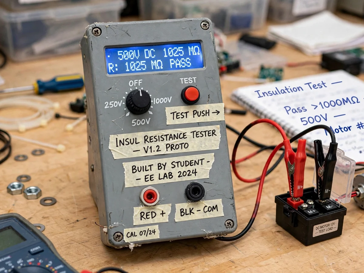
Insulated leads with crocodile clips connected across de-energised equipment.
Follow the working sequence
How it works
- The user connects the test leads across the de-energised equipment to be tested, selects 250 V, 500 V or 1000 V (design target) with the rotary switch, and confirms the equipment is disconnected from any live supply.
- Pressing the TEST button enables the DC-DC converter stage, which steps the low-voltage supply up to the selected high test voltage through a current-limited output network.
- The test voltage is applied across the insulation under test, and a small leakage current flows in proportion to how well the insulation resists the applied voltage.
- A high-voltage divider and sensing resistor network scales the leakage signal down to a safe low-voltage range that the microcontroller ADC can sample without damage.
- Firmware averages several ADC samples, applies the calibrated divider ratio, and computes insulation resistance using R = V / I, then formats the result in kΩ, MΩ or GΩ as appropriate.
- The resistance value and selected test voltage are shown on the LCD, while a real-time clock provides the date and time for the measurement record.
- On releasing TEST, the reading is written to the log with its timestamp, the converter output is disabled, and the discharge path bleeds residual charge from the device under test before the leads are removed.
Tech stack:
- Microcontroller (ATmega328P / Arduino-compatible board)
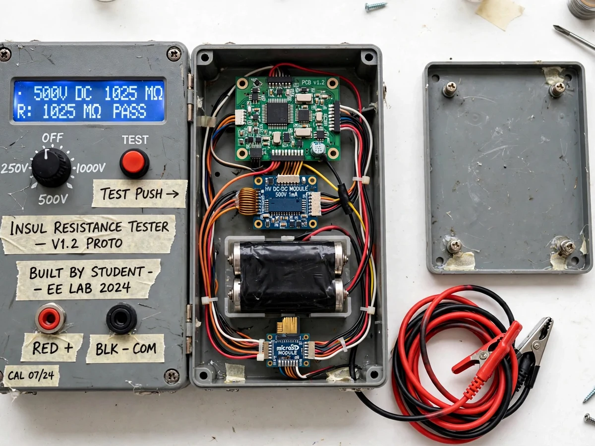
- High-voltage DC-DC converter stage
- Precision voltage divider · current sensing network
- 16x2 character LCD display
- DS3231 real-time clock module
- MicroSD card logging module
- Rotary selector switch · TEST push-button
- Arduino IDE · Embedded C firmware
| Parameter | Value |
|---|---|
| Test voltages | 250 V, 500 V, 1000 V DC (design target, selectable) |
| Resistance range | 0.01 MΩ to 2000 MΩ (design target) |
| Display | 16x2 character LCD |
| Controller | ATmega328P-based microcontroller board |
| Output current | Current-limited, approximately 1 mA maximum (design target) |
| Logging | Timestamped records to microSD / controller memory |
| Time source | DS3231 RTC, battery-backed |
| Power supply | 9 V DC adapter or battery pack (expected) |
| Test leads | Silicone leads with crocodile clips, rated above test voltage |
| Enclosure | Handheld ABS project enclosure (approximate) |
Project features
- [Selectable test voltage] A rotary selector chooses 250 V, 500 V or 1000 V as design-target test voltages, so the same prototype can demonstrate low-voltage winding checks and higher-voltage cable insulation tests in one setup.
- [High-voltage DC-DC generation stage] A step-up DC-DC converter stage generates the selected test voltage from a low-voltage supply, with current limiting built into the design so short-circuit current at the probes stays restricted.
- [Leakage current measurement] A precision sensing network measures the microamp-level leakage current flowing through the device under test, which is the raw quantity from which insulation resistance is calculated.
- [Automatic resistance calculation] The microcontroller samples the sensed voltage, applies the divider ratio and Ohm's law calculation in firmware, and converts the reading to kilohms, megohms or gigohms for direct display.
- [LCD result display] A character LCD shows the selected test voltage, measured insulation resistance and test status together, removing the parallax and scale-reading errors of an analogue insulation meter.
- [Timestamped data logging] Each completed test is stored with date, time, test voltage and resistance value in microcontroller memory or on a microSD card, and can be retrieved later for record sheets and comparison.
- [Test push-button with discharge indication] Testing starts only while the TEST button is deliberately pressed, and a discharge indicator prompts the user to wait after a test so stored charge in capacitive loads can bleed away safely.
What is included
- Working insulation resistance tester prototype
- Test leads with insulated crocodile clips
- Firmware / source code for the microcontroller
- Circuit diagram and wiring documentation
- Component list with part values and ratings
- Calibration procedure using known high-value resistors
- Project report PDF (background, methodology, circuit explanation, results format)
- PPT presentation for final review
- Viva Q&A preparation document (insulation testing, DC-DC conversion, divider sensing, safety)
Limitations & prerequisites
- This is an academic prototype, not a certified or commercial Megger-type instrument — it must not be used for compliance, safety-certification or industrial acceptance testing.
- Test voltages and resistance range are design targets; actual readings depend on component tolerances, divider resistor accuracy and the calibration procedure followed.
- Never connect the tester to a live or energised circuit — the equipment under test must be fully isolated and de-energised before and during every test.
- High voltage is hazardous even at limited current: probes must not be touched during a test, and capacitive loads must be discharged after testing before handling.
- Readings drift with temperature, humidity and surface contamination on the test object, as with any insulation measurement — results are comparative, not absolute laboratory values.
- Calibration against known resistors is a buyer-run procedure documented in the manual; it is not a factory or laboratory calibration certificate.
- Very low insulation resistances and continuous short circuits are outside the intended measurement focus and will read at the bottom of the range.
Frequently Asked Questions
Is this project suitable for a final-year project?
Yes, for Electrical Engineering programs. It combines high-voltage generation, precision sensing, microcontroller interfacing, real-time clock logging and safety design in one build, giving strong viva material across power systems, measurements and embedded topics, with a working demonstration that is easy to explain stage by stage.
How is safety handled with 1000 V in a student project?
Safety is handled by design and procedure together: the output is current-limited, testing needs a deliberate press of the TEST button, leads and clips are insulated and rated above the test voltage, the manual bans use on live circuits, and a discharge step follows every test. Even so, the voltage must always be treated as hazardous and handled only as instructed.
Which controller is used and why?
An ATmega328P-based board is used because it has enough ADC channels for the sensing network, enough digital pins for the LCD, selector and buttons, and simple interfaces for the DS3231 clock and microSD module. The firmware is written in Embedded C using the Arduino IDE, so students can read, modify and explain every calculation.
How is the resistance actually calculated?
The applied test voltage is known from the selector setting, and the leakage current is inferred from the voltage developed across the sensing network after scaling by the divider ratio. Firmware averages the ADC samples, removes offset, and applies R = V / I. Accuracy depends on divider resistor tolerance and on completing the documented calibration with known resistors.
Can the test voltages or logging be changed?
The selector positions and firmware voltage settings are configurable in code, and the log format can be extended with extra fields such as equipment name. Adding a wireless upload of logs or a graphical display is possible as a separate customisation, but it is not part of the base build described here.
What will I receive with the project?
The working prototype with test leads, the complete firmware source code, circuit and wiring documentation, the component list, a written calibration procedure, the project report and PPT, and a viva Q&A document. Demonstration guidance explains how to test sample resistors, cables and a small motor winding safely during the review.
Components & software requirements
- Microcontroller (ATmega328P / Arduino-compatible board)
- High-voltage DC-DC converter stage
- Precision voltage divider · current sensing network
- 16x2 character LCD display
- DS3231 real-time clock module
- MicroSD card logging module
- Rotary selector switch · TEST push-button
- Arduino IDE · Embedded C firmware
Delivery information
Built-to-order project. Delivery timeline is shared after order confirmation based on current queue.
Support terms
Complete documentation, setup guide, and viva preparation included. Support for setup and explanation provided.
Download free synopsis (PDF)
Enter your name and email — the synopsis PDF downloads immediately. We may send occasional project updates; no spam, unsubscribe anytime.