
More project photos (2)
The problem
In a shaper or slotter, the tool must cut slowly on the working stroke and race back on the return stroke — idle time saved is production gained. The Whitworth crank-and-slotted-lever mechanism achieves this with a single rotating crank: a pin on the crank wheel slides in the slot of a long pivoted lever, and because the crank's rotation is split unequally between the two extreme positions of the lever, the ram it drives spends more time cutting than returning. In theory of machines classes this is usually a diagram and a timing-ratio formula, and most students never feel the asymmetry they are asked to compute. This project builds a bench-top demonstration model of the mechanism: a hand-cranked (optionally motor-driven) crank wheel, slotted lever, connecting link and guided ram on a fabricated steel frame. Turning the crank makes the timing difference visible and measurable — the student times both strokes, computes the cutting-to-return ratio, and compares it with the geometric prediction.
How it works
- The student turns the hand crank (or runs the optional DC gear motor) at a steady pace, rotating the crank wheel at approximately constant angular velocity.
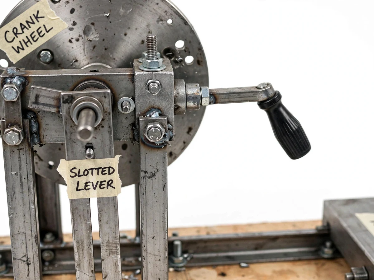
- A pin fixed at about 60 mm radius on the wheel slides in the slot of the slotted lever, converting uniform rotation into oscillating lever motion about the lever's fixed pivot below.
- The lever's extreme positions occur where the crank pin is tangent to the swing geometry — the crank sweeps a larger angle during the working stroke than during the return stroke, which is the source of the quick-return effect.
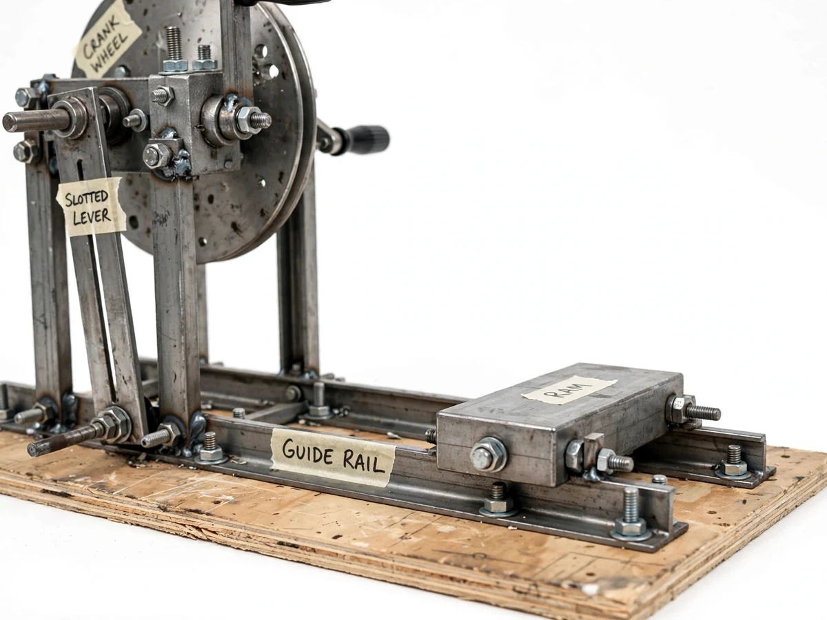
- The top of the slotted lever drives the connecting link, which pushes and pulls the ram block along the guide rails: a slow forward cutting stroke followed by a quicker return.
- The student times one full cycle with a stopwatch — the working stroke lasts about 1.7 times as long as the return stroke, the design target from the nominal geometry (crank radius 60 mm, crank-centre distance approx. 150 mm).
- Measured times are entered in the timing sheet and compared with the geometric prediction; the student repeats at different crank speeds to show the ratio is a property of the geometry, not of speed.
Tech stack:
- Mild steel flats & angles (fabricated frame)
- Steel crank wheel with crank pin
- Slotted lever & connecting link (mild steel)
- Ram block with twin guide rails
- 608 ball bearings (crank shaft)
- Hand-crank handle (motor-ready)
- 12 V DC gear motor, approx. 30 RPM (optional drive)
- Masking-tape labels, M6/M8 fasteners
| Parameter | Value |
|---|---|
| Base board | Approx. 600 × 400 × 18 mm plywood |
| Frame | Bolted mild steel angles (design target) |
| Crank wheel | Approx. 140 mm diameter steel disc |
| Crank radius | Approx. 60 mm (design target) |
| Crank-centre distance | Approx. 150 mm (design target) |
| Slotted lever | Approx. 450 mm mild steel flat |
| Ram travel | Approx. 180 mm stroke (design target) |
| Timing ratio (cutting : return) | Approx. 1.7 : 1 (design target from geometry) |
| Drive | Hand crank; optional 12 V DC gear motor, approx. 30 RPM |
| Bearings & fasteners | 608 ball bearings; M6/M8 nuts & bolts |
Project features
- [True Whitworth geometry] A crank pin sliding in the slotted lever produces the genuine quick-return asymmetry from the mechanism's geometry — the same principle the report derives, so the demonstration and the theory agree.
- [Visible cutting vs return timing] The ram's slow working stroke and quick return are plain to see; with a stopwatch the student times both and computes the cutting-to-return ratio against the design target of approximately 1.7:1.
- [Hand crank drive, motor-ready] A hand-crank handle on the crank wheel gives direct control for demonstrations and stroke timing; an optional 12 V DC gear motor (approx. 30 RPM) can be fitted for continuous running.
- [Guided ram and connecting link] The ram block runs between two parallel guide rails, driven by the connecting link from the slotted lever — showing how uniform rotary input becomes straight-line reciprocating output.
- [Bearing-mounted crank] 608 ball bearings on the crank shaft keep rotation smooth and low-friction, so the timing asymmetry is not masked by jerky motion.
- [Labeled demonstration stations] Handwritten masking-tape labels mark the crank wheel, slotted lever, connecting link, ram and guide rails for clear viva and classroom demonstration.
- [Timing observation sheet] A student-run test sheet with columns for crank speed, cutting-stroke time, return-stroke time and computed ratio, so the demonstration yields the student's own results.
What is included
- Fabricated Whitworth mechanism model (frame, crank wheel, slotted lever, connecting link, ram, guide rails)
- Hand-crank handle fitted; mounting provision for the optional DC gear motor
- Handwritten masking-tape labels on all key stations
- Stroke-timing observation sheet with a worked example
- Project report PDF (Whitworth geometry, derivation of the timing ratio, build procedure, test results)
- PPT presentation for final review
- Viva Q&A preparation document (quick-return theory, timing-ratio derivation, shaper/slotter applications)
Limitations & prerequisites
- This is a demonstration model, not a working shaper — there is no cutting tool or workpiece; it demonstrates the drive timing, not metal cutting.
- The approx. 1.7:1 timing ratio is a design target from the nominal geometry; the student's measured values depend on their own timing and on build tolerances of about ±2–3 mm on link dimensions.
- Hand-cranked speed varies between operators, so the ratio — not the absolute stroke times — is the repeatable result; the report states this explicitly.
- Slot-to-pin clearance of about 0.5–1 mm in the built model introduces a small amount of play; the lever dwell this causes is discussed in the report rather than hidden.
- The bolted mild-steel assembly weighs about 8–10 kg (design target) and must sit on a stable bench during demonstration.
- The optional motor drive runs at a fixed approx. 30 RPM; no speed control is included unless ordered.
Frequently Asked Questions
What is the quick-return effect and why does it matter?
The Whitworth crank-and-slotted-lever mechanism converts the crank's uniform rotation into ram motion where the working (cutting) stroke takes longer than the return stroke. Shapers and slotters use it because the tool cuts in only one direction — the idle return is made as short as possible to save time. This model makes that timing asymmetry visible and measurable.
How is the timing ratio calculated?
From the geometry: the crank sweeps a larger rotation angle during the working stroke and a smaller one during the return, while rotating at constant speed. With the model's nominal crank radius (60 mm) and crank-centre distance (150 mm), the cutting-to-return time ratio works out to approximately 1.7:1. The report carries the full derivation, and the timing sheet lets the student verify it with a stopwatch.
Is the mechanism driven by hand or by motor?
The crank wheel carries a hand-crank handle as standard, which is best for demonstrations and for timing strokes. An optional 12 V DC gear motor (approx. 30 RPM) can be fitted for hands-free continuous running.
Does the model actually cut material?
No. It is a kinematics demonstration model — it shows how a shaper's drive mechanism moves and why the return stroke is quicker, without a cutting tool or workpiece. Actual metal cutting would need a real machine tool.
Can the stroke length be changed?
The stroke length follows from the crank radius and lever proportions. The crank pin sits at a fixed radius of about 60 mm, so the ram stroke is approximately 180 mm by design; an adjustable crank radius is documented as future scope.
Is this project suitable for a final-year project?
Yes — for Mechanical Engineering programs. It covers kinematic analysis of a real industrial mechanism, hands-on fabrication, bearing selection, and experimental verification of a theoretical timing ratio. Suitable for B.E./B.Tech final-year projects in Mechanical Engineering.
Components & software requirements
- Mild steel flats & angles (fabricated frame)
- Steel crank wheel with crank pin
- Slotted lever & connecting link (mild steel)
- Ram block with twin guide rails
- 608 ball bearings (crank shaft)
- Hand-crank handle (motor-ready)
- 12 V DC gear motor, approx. 30 RPM (optional drive)
- Masking-tape labels, M6/M8 fasteners
Delivery information
Built-to-order project. Delivery timeline is shared after order confirmation based on current queue.
Support terms
Complete documentation, setup guide, and viva preparation included. Support for setup and explanation provided.