
More project photos (2)
The problem
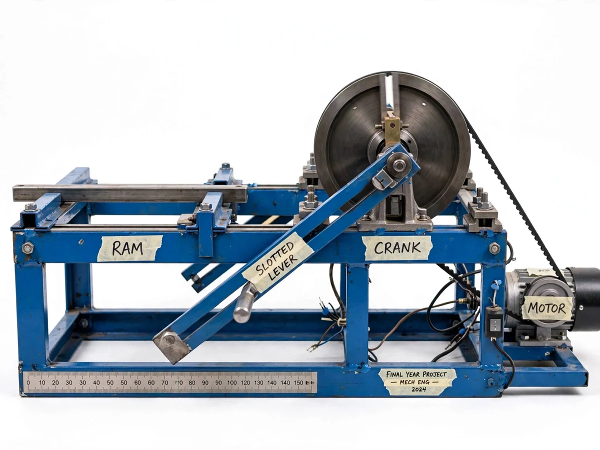
In metal shaping, the cutting tool should move slowly while cutting and return quickly while idle, wasting as little time as possible on the non-cutting stroke. The Whitworth quick-return mechanism achieves this with pure kinematics: a crank rotating at constant speed drives a slotted lever through a sliding block, and the drive geometry makes the forward stroke of the ram slower than its return. The ratio of cutting time to return time — the timing ratio — follows directly from the crank-circle geometry and changes with the crank radius, a result every theory-of-machines student derives on paper. This project turns that derivation into hardware: a bench-top rig with an adjustable crank, a slotted lever and a guided ram, driven by a single-phase motor through a belt reduction. The student sets the crank radius, times the actual cutting and return strokes, and compares the measured timing ratio with the theoretical value from the crank geometry.
How it works
- The single-phase motor drives the crank shaft at a reduced, constant speed through the V-belt drive.
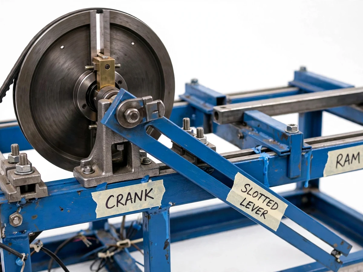
- The crank pin, set at the chosen radius in the crank disc slot, carries a sliding block that engages the slot of the slotted lever.
- As the crank rotates uniformly, the sliding block pushes the slotted lever through unequal angles on the forward and return halves of the revolution.
- The top of the slotted lever drives the connecting rod, which moves the ram in its guideways — slow on the cutting stroke, fast on the return stroke.
- The student times the cutting and return strokes over several revolutions and computes the measured timing ratio.
- The measured ratio is compared with the theoretical ratio derived from the crank-radius geometry in the manual, then the crank radius is changed to repeat the study.
Tech stack:
- MS angle and plate frame (fabricated)
- Crank disc with radial slot and sliding block
- Slotted lever, connecting rod and guided ram
- 0.5 HP single-phase induction motor
- V-belt and pulley reduction drive
- Plummer block bearings
- Digital tachometer and graduated stroke scale
| Parameter | Value |
|---|---|
| Crank radius settings | 25 / 40 / 55 mm (approximate, marked) |
| Stroke length | Approximately 180–260 mm (depends on crank setting) |
| Timing ratio | Approximately 1.4:1 to 2:1 (design target, varies with crank radius) |
| Crank speed | Approximately 30–40 rpm (design target) |
| Motor | 0.5 HP single-phase induction motor (nameplate rating) |
| Overall size | Approximately 900 × 400 × 600 mm |
| Weight | Approximately 45 kg (design target) |
Project features
- [Adjustable crank radius] The crank pin rides in a radial slot on the crank disc and clamps at marked positions, so the timing ratio can be changed and the study repeated at different settings.
- [True slotted-lever drive] A genuine crank-and-slotted-lever arrangement: the sliding block on the crank pin engages the lever slot, and the lever top drives the connecting rod to the ram.
- [Guided ram with stroke scale] The ram slides in machined guideways beside a graduated scale, so stroke length and stroke direction are read directly off the rig.
- [Timing-ratio measurement] Stroke times are timed with the supplied digital tachometer and stopwatch procedure, letting the student compare the measured cutting/return ratio against theory.
- [Belt-reduction drive] A 0.5 HP single-phase induction motor drives the crank shaft through a V-belt reduction, giving a slow, safe, easily observable crank speed.
- [Fabrication drawings] Dimensioned 2D drawings of the frame, crank disc, slotted lever, ram and guideways are supplied for the report and viva.
- [Velocity-analysis manual] A worked manual deriving the timing ratio from crank geometry, with blank calculation sheets the student fills from their own readings.
What is included
- Fully fabricated and assembled quick-return rig
- Dimensioned fabrication drawings (frame, crank, lever, ram)
- Theory and velocity-analysis manual with calculation sheets
- Digital tachometer and stopwatch timing procedure card
- Project report PDF (background, kinematics, methodology, results format)
- PPT presentation for final review
- Viva Q&A preparation document (timing-ratio derivation, inversions, applications)
Limitations & prerequisites
- A demonstration rig, not a production shaper — it performs no actual metal cutting.
- The timing ratio is verified from the student's own timing; no ratio is claimed as measured before the build.
- Stopwatch timing carries human reaction error; the manual includes a repeat-and-average procedure to reduce it.
- Belt slip and bearing friction are not modeled in the theoretical ratio — small deviations are expected and discussed in the report.
- Fixed belt reduction: crank speed is not variable in the base build (a VFD drive is listed as future scope).
- Bench-top scale: overall size suits a lab bench, not a workshop-floor demo.
Frequently Asked Questions
What is the timing ratio, and why does it matter?
The timing ratio is cutting-stroke time divided by return-stroke time. In shaping, only the cutting stroke does useful work, so a ratio above 1 (typically 1.5–2) means less idle time per cycle. The rig lets the student measure this ratio and see how crank radius changes it.
How is the timing ratio measured on the rig?
The student times the forward and return strokes over several crank revolutions using the tachometer and stopwatch procedure, then divides the totals. Repeating and averaging keeps the human timing error small.
Where is this mechanism actually used?
In crank-driven shaping machines, slotting machines and some mechanical presses — anywhere a slow working stroke and fast return stroke are wanted from a constant-speed drive.
Can the crank radius be changed during a demo?
Yes — the crank pin clamps at marked positions along the crank disc's radial slot, so the timing-ratio study can be repeated at different settings in one session.
Is this project suitable for a final-year project?
Yes — for Mechanical, Production and Manufacturing programs. It connects theory-of-machines kinematics to a working model with real measurement and analysis. Suitable for B.E./B.Tech final-year projects in Mechanical, Production and Manufacturing Engineering.
Components & software requirements
- MS angle and plate frame (fabricated)
- Crank disc with radial slot and sliding block
- Slotted lever, connecting rod and guided ram
- 0.5 HP single-phase induction motor
- V-belt and pulley reduction drive
- Plummer block bearings
- Digital tachometer and graduated stroke scale
Delivery information
Built-to-order project. Delivery timeline is shared after order confirmation based on current queue.
Support terms
Complete documentation, setup guide, and viva preparation included. Support for setup and explanation provided.