
More project photos (2)

The problem
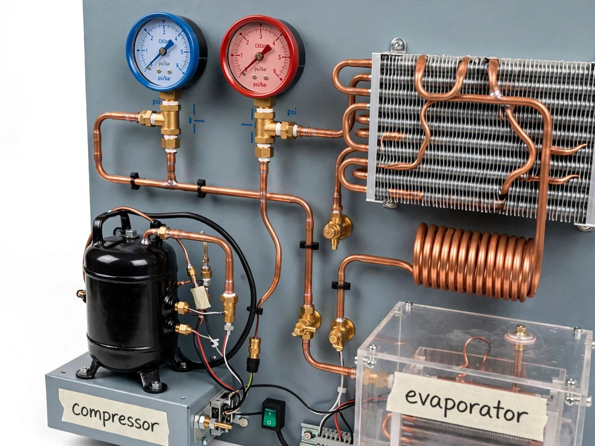
The vapour compression cycle is the most examined topic in refrigeration courses and the least touched — students draw the p-h diagram repeatedly but rarely stand in front of a running loop with gauges. Commercial trainers are costly and usually locked in the thermal lab, so the cycle stays theoretical. This project builds a student-scale trainer: a hermetic compressor, a finned-tube condenser, a capillary-tube expansion device and an evaporator coil inside a transparent cold chamber, all piped in copper and mounted on a panel with suction and discharge pressure gauges and thermometers. The student starts the unit, watches the discharge pressure climb and frost form on the evaporator, logs the four key temperatures and two pressures over time, and works out the COP from their own data using the procedure's worksheet.
How it works
- The trainer is switched on and the student traces the refrigerant path on the panel: compressor → condenser → capillary tube → evaporator → back to the compressor.
- As the unit runs, the discharge gauge climbs, the condenser warms up, and frost begins forming on the evaporator coil inside the cold chamber.
- The student logs suction and discharge pressures plus the four thermometer readings at fixed time intervals until the chamber temperature stabilises.
- The cooling curve (chamber temperature vs time) is plotted from the log, showing the pull-down behaviour of the cycle.
- Using the worksheet, the student computes the refrigerating effect and the coefficient of performance from their own pressure–temperature data.
- The run is repeated with the chamber door briefly opened (a controlled load change) to show how the cycle responds, and both runs are compared in the report.
Tech stack:
- Hermetic compressor unit
- Finned-tube condenser
- Capillary tube expansion device
- Evaporator in acrylic cold chamber
- Suction and discharge pressure gauges
- Thermometer measurement points
- Brazed copper piping with service valves
- COP experiment manual and worksheet
| Parameter | Value |
|---|---|
| Cycle | Vapour compression, single stage (design) |
| Refrigerant | R134a (design, builder-charged) |
| Compressor | Hermetic, approximately 1/6 hp (design) |
| Condenser | Finned copper tube, air-cooled (design) |
| Expansion device | Capillary tube (design) |
| Gauges | Suction and discharge, psi/bar dials (design) |
| Cold chamber | Transparent acrylic, approximately 300 × 300 × 300 mm (design) |
| Power | 230 V AC single phase (design) |
Project features
- [Hermetic compressor] A sealed compressor unit forms the heart of the loop, mounted on anti-vibration pads with its electricals wired to the panel switch.
- [Finned-tube condenser] A finned copper-tube condenser rejects heat to the room air, visibly warm to the touch while running.
- [Capillary tube expansion] A capillary tube meters the refrigerant into the evaporator — the simplest expansion device, ideal for studying the throttling process.
- [Transparent cold chamber] The evaporator coil sits inside a clear acrylic chamber so frost formation and cooling are directly visible during the run.
- [Suction and discharge gauges] Two panel pressure gauges read the low and high sides of the cycle continuously.
- [Thermometer points] Thermometers at the compressor suction/discharge, condenser outlet and inside the cold chamber capture the four key temperatures.
- [Copper piping with valves] The full circuit is brazed copper with service valves, laid out on the panel so the refrigerant path can be traced by hand.
- [COP worksheet] The experiment manual walks through logging, plotting the cooling curve, and computing the coefficient of performance from the student's readings.
What is included
- Assembled vapour compression refrigeration trainer (full circuit on panel)
- Hermetic compressor with panel switch and wiring
- Suction and discharge pressure gauges
- Thermometers at four measurement points
- Transparent evaporator cold chamber
- Piping layout drawing and component list
- Experiment manual with logging sheets and COP worksheet
- Project report PDF (background, cycle theory, build, experiment methodology, results format)
- PPT presentation for final review
- Viva Q&A preparation document (vapour compression cycle, COP, capillary vs TXV, subcooling/superheat)
Limitations & prerequisites
- A teaching trainer, not a commercial refrigeration unit — cooling capacity is sized for the demo chamber, not for practical refrigeration loads.
- The COP is computed by the student from their own readings; no COP figure is claimed for the trainer itself.
- Room temperature and humidity affect pull-down time and frost formation — the manual asks the student to record ambient conditions with each run.
- Refrigerant charging and any service work are builder-side only; the student unit is sealed and needs no handling of refrigerant.
- Pressure gauges are dial instruments with normal reading uncertainty; the worksheet includes an uncertainty note the student completes.
Frequently Asked Questions
What will I actually see when it runs?
The discharge gauge rising, the condenser getting warm, frost creeping across the evaporator coil in the clear chamber, and the chamber thermometer falling — the whole cycle made visible in about 20–30 minutes.
How is COP calculated from the readings?
From the refrigerating effect (from the measured temperatures and the refrigerant property tables referenced in the manual) divided by the compressor work input. The worksheet carries the student through it step by step.
Why a capillary tube instead of a thermostatic valve?
The capillary is the simplest expansion device — no moving parts, nothing to adjust — which keeps the trainer robust and lets the experiment focus on the cycle itself rather than valve tuning.
Is it safe to operate?
The refrigerant circuit is sealed and builder-charged; the student only operates the panel switch and reads gauges and thermometers. Electricals are enclosed with a single ON/OFF control.
What does opening the chamber door demonstrate?
A sudden heat load: pressures shift, the compressor works harder, and the pull-down restarts — a vivid, measurable look at how the cycle responds to load change.
Is this project suitable for a final-year project?
Yes — for Mechanical Engineering programs. It combines thermal hardware assembly, instrumentation, and cycle analysis, and the report is built on the student's own logged pressures, temperatures and computed COP. Suitable for B.E./B.Tech final-year projects in Mechanical Engineering.
Components & software requirements
- Hermetic compressor unit
- Finned-tube condenser
- Capillary tube expansion device
- Evaporator in acrylic cold chamber
- Suction and discharge pressure gauges
- Thermometer measurement points
- Brazed copper piping with service valves
- COP experiment manual and worksheet
Delivery information
Built-to-order project. Delivery timeline is shared after order confirmation based on current queue.
Support terms
Complete documentation, setup guide, and viva preparation included. Support for setup and explanation provided.