
More project photos (2)
The problem
Electric potter's wheels are convenient, but they tie a craft to the mains socket: in rural training centres, craft workshops and college clay labs, a power cut or a missing extension board ends the session. Imported treadle wheels exist, but they are expensive and rarely arrive with any engineering documentation a student can learn from. This project builds the human-powered alternative from first principles — a foot treadle, a slider-crank, a heavy flywheel and a belt-driven spindle, all on a welded MS angle frame. The operator pumps the pedal while both hands stay free to throw; the flywheel's inertia carries the crank through its dead-centre and evens out the pulsing stroke into a steady wheel-head rotation. Every number in the build — crank radius, flywheel rim mass, belt ratio — is sized by hand calculation, so the machine doubles as a working demonstration of machine-design theory: kinematics, energy storage and power transmission in one rig.
Pumps the treadle and centers clay on the spinning head.
Follow the working sequence
How it works
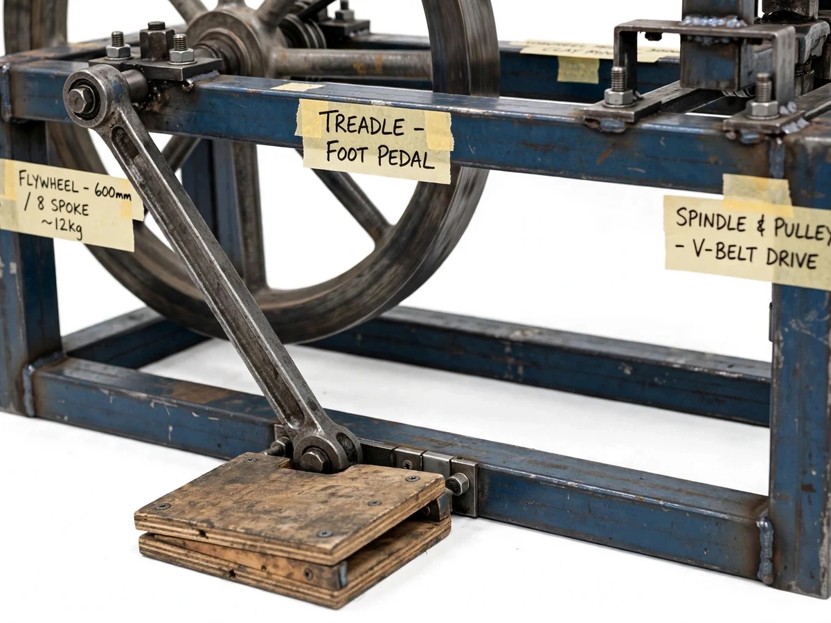
- The operator rests one foot on the ~600 mm wooden treadle pedal and pumps it through a stroke of roughly 100–150 mm at the pedal tip (approximate), the way generations of potters have done.
- The connecting rod carries each down-stroke to the crank pin on the flywheel shaft; the slider-crank geometry converts the reciprocating push into rotation, with the flywheel's inertia doing the work through the dead-centre where the crank cannot.
- The ~600 mm flywheel, with its heavy ~12 kg rim (approximate, design target), spins up over the first few strokes and stores the energy, so the speed no longer rises and falls with each pump.
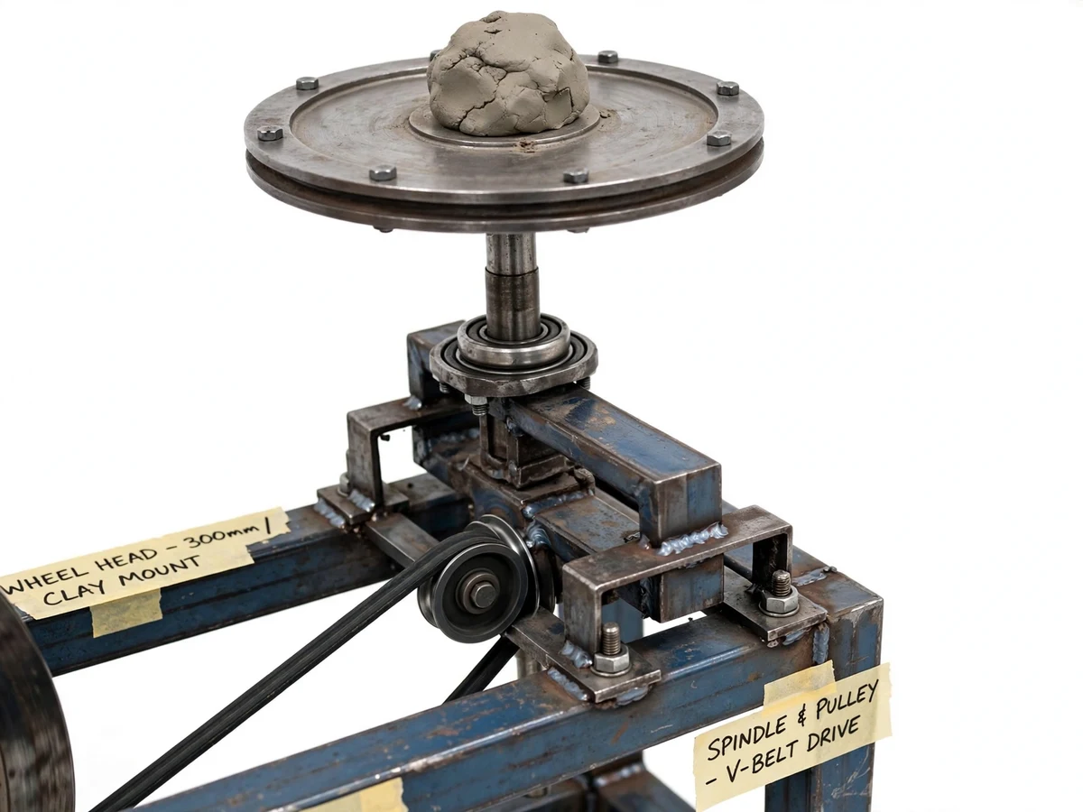
- A V-belt on the flywheel shaft pulley drives the smaller spindle pulley at roughly a 1:2 step-up (design target), so the vertical spindle turns faster than the flywheel.
- The spindle — carried by rolling-element bearings with a thrust bearing taking the axial clay load — spins the 300 mm wheel head at about 80–150 RPM at a comfortable treadling cadence (design target).
- The operator places a prepared clay lump on the spinning head and centers it with both hands; speed is trimmed simply by treadling faster or slower, and the flywheel spins the head down gently when the pedal stops.
Tech stack:
- MS angle and box-section frame fabrication
- Arc welding (SMAW) with bolted bearing joints
- Slider-crank linkage kinematics
- Flywheel inertia and energy-storage sizing
- V-belt drive selection and ratio design
- Plummer block and thrust bearing selection
- Cast-iron wheel head machining and facing
- Wooden treadle fabrication with anti-slip surface
| Parameter | Value |
|---|---|
| Wheel head diameter | 300 mm (design target) |
| Wheel head material | Cast iron / mild steel disc, faced true (design target) |
| Flywheel diameter | 600 mm (design target) |
| Flywheel rim mass | ~12 kg (approximate, design target) |
| Treadle pedal length | 600 mm (design target) |
| Treadle stroke at pedal tip | 100–150 mm (approximate) |
| Drive | Single-stage V-belt (design target) |
| Drive ratio | ~1:2 step-up, flywheel to spindle (design target) |
| Spindle speed | 80–150 RPM at comfortable treadling (design target) |
| Bearings | Plummer/pillow blocks on flywheel shaft; thrust bearing under spindle (design target) |
| Frame | MS angle 40×40×5 mm, welded (design target) |
| Overall footprint | ~1100 × 700 mm (approximate) |
| Height to wheel head | ~750 mm (approximate) |
| Clay lump capacity | Up to ~5 kg (design target; centering heavy lumps needs practice) |
| Power source | Human foot power only — no electricity required |
Project features
- [Pure human power] No electric motor anywhere in the build. The operator's foot supplies all the energy, so the wheel works in a courtyard, a craft fair stall or a lab with an unreliable mains supply.
- [Flywheel energy smoothing] The ~600 mm flywheel carries a heavy rim (approximate 12 kg, design target) whose stored inertia evens out the treadle's pulsing stroke and carries the crank through its dead-centre positions.
- [Slider-crank drive conversion] A connecting rod links the treadle pedal to a crank pin on the flywheel shaft, converting the operator's up-and-down pumping into continuous rotation with mechanically correct timing.
- [Belt step-up to the spindle] A V-belt runs from the large flywheel shaft pulley to a smaller spindle pulley at roughly a 1:2 step-up (design target), multiplying the flywheel's rotation into the wheel head's working speed.
- [Cast-iron clay centering head] A ~300 mm diameter faced steel/cast-iron disc tops the vertical spindle, giving a flat, true-running surface for centering and throwing clay lumps.
- [Welded MS angle frame] The whole machine stands on a rigid frame fabricated from 40×40×5 mm MS angle (design target), with plummer/pillow-block bearings carrying the flywheel shaft and a thrust bearing under the spindle.
- [Adjustable crank radius] The crank pin position can be re-set along the crank arm (configurable), trading pedal effort against flywheel speed to suit different operators.
What is included
- Working treadle-powered potter's wheel, fabricated fresh for your order
- Dimensioned fabrication drawings: frame, flywheel, crank, spindle and belt-drive layout
- Design calculation sheet: crank geometry, flywheel inertia sizing, belt and bearing selection
- Clay centering technique guide and basic throwing notes
- Belt tensioning, bearing greasing and maintenance guide
- Project report PDF (background, mechanism design, calculations, testing)
- PPT presentation for final review
- Viva Q&A preparation document (slider-crank, flywheel theory, belt drives, bearings)
Limitations & prerequisites
- All RPM, speed and mass figures are design targets for the built-to-order machine — verify actual spindle speed with a tachometer during commissioning rather than quoting them as measured results.
- Centering clay has a genuine learning curve: lumps above ~3 kg wobble badly in beginners' hands, and that is an operator-skill matter, not a machine defect.
- There is no electric motor and no speed-control electronics; speed is set entirely by treadle cadence, so holding an exact RPM takes practice.
- The flywheel rim is heavy (~12 kg approximate); the machine needs a flat, stable floor and the flywheel sweep area must be kept clear while it spins.
- Belt slip can occur if the belt runs slack or if clay water splashes onto the drive — checking tension is part of routine use.
- Raw steel surfaces will rust in a humid workshop unless oiled periodically; paint touch-ups are the owner's maintenance.
- This is an academic prototype for study and demonstration, not a production pottery machine rated for sustained commercial throwing.
Frequently Asked Questions
Is this project suitable for a final-year project?
Yes — for Mechanical, Production and Manufacturing programs. It demonstrates slider-crank kinematics, flywheel energy-storage sizing, V-belt drive design, bearing selection and welded frame fabrication, all verifiable by hand calculation and physical testing. The build, the calculation sheet and the viva Q&A document map directly onto machine-design coursework.
Does it really work with no electricity at all?
Completely. The operator's foot supplies 100% of the energy through the treadle, and the heavy flywheel stores that energy between strokes to keep the wheel head turning steadily. It works in a courtyard, at a craft fair or in any lab with an unreliable mains supply — no motor, no wiring, no power bill.
How fast does the wheel head actually spin?
The design target is 80–150 RPM at a comfortable treadling cadence, reached through roughly a 1:2 belt step-up from the flywheel. Treat this as a target, not a measured figure: the buyer should check the real speed with a tachometer during commissioning, since cadence, belt tension and clay load all shift the actual number.
Can a beginner center clay on it?
Yes, with practice. Start with small 1–2 kg lumps — they center easily and forgive mistakes. Heavier lumps near the 5 kg design capacity demand real technique and will wobble in untrained hands. The included centering guide walks through wedging, coning and steadying, but expect the first sessions to be humbling.
Can an electric motor be added later?
It can, but it is not part of this build — the base machine is deliberately treadle-only, and that is its engineering point. A motorized variant with a clutch or a detachable motor drive can be developed as a customization on request; it would change the belt layout and the frame drawings.
What maintenance does the wheel need?
Little, but regular: check V-belt tension and re-tension as it beds in, grease the plummer-block bearings periodically, keep clay water off the belt, and oil exposed steel surfaces so they do not rust. The treadle hinge pin and crank pin should be inspected for wear each semester of heavy use.
Components & software requirements
- MS angle and box-section frame fabrication
- Arc welding (SMAW) with bolted bearing joints
- Slider-crank linkage kinematics
- Flywheel inertia and energy-storage sizing
- V-belt drive selection and ratio design
- Plummer block and thrust bearing selection
- Cast-iron wheel head machining and facing
- Wooden treadle fabrication with anti-slip surface
Delivery information
Built-to-order project. Delivery timeline is shared after order confirmation based on current queue.
Support terms
Complete documentation, setup guide, and viva preparation included. Support for setup and explanation provided.
Download free synopsis (PDF)
Enter your name and email — the synopsis PDF downloads immediately. We may send occasional project updates; no spam, unsubscribe anytime.