
More project photos (2)
The problem
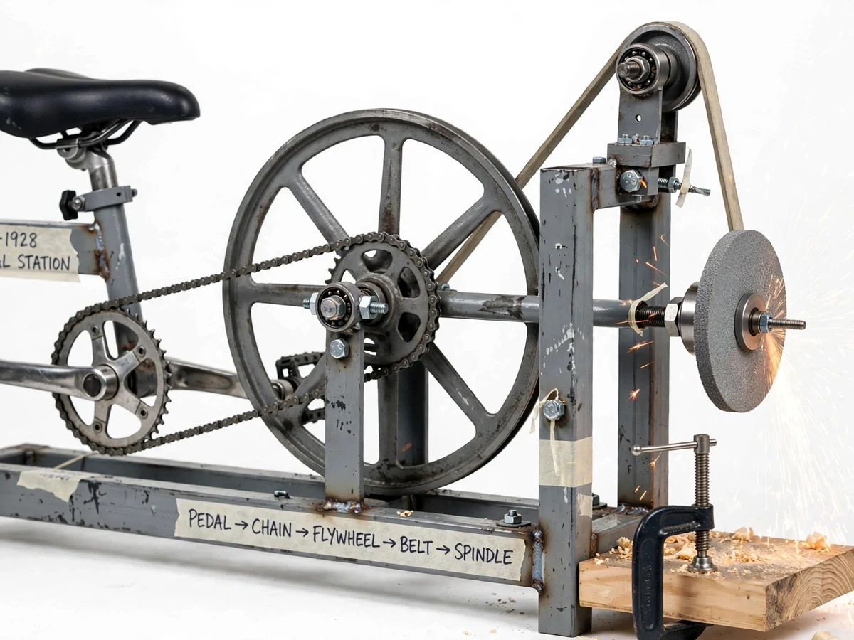
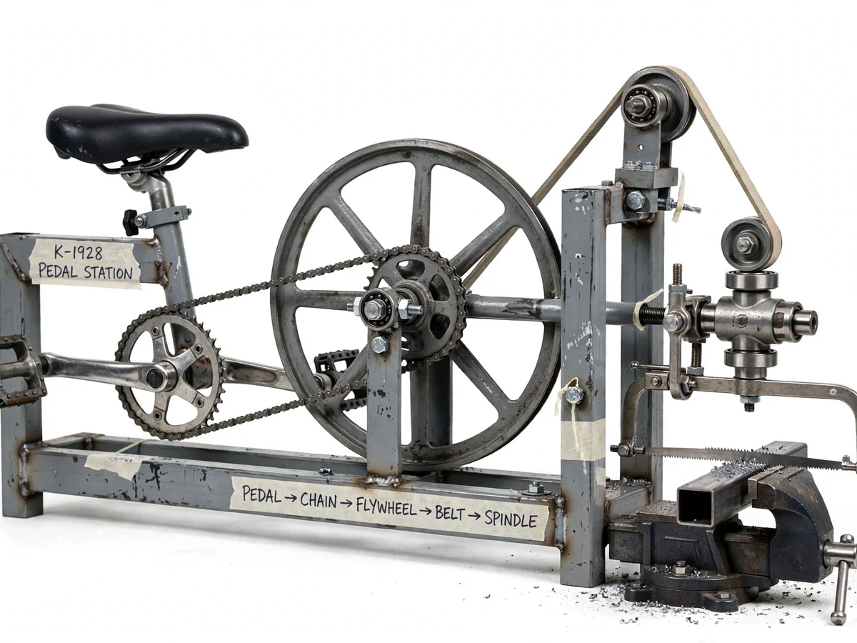
The Pedal-Powered Multi-Tool Workshop Station is a human-powered workstation built around a bicycle pedal crank, a chain drive, a heavy spoked flywheel and a belt drive that delivers rotary power to one working spindle head. Three interchangeable attachments bolt onto that spindle: a drill chuck for drilling wood and thin sheet, a grinding wheel for sharpening and deburring, and a reciprocating hacksaw frame driven through a crank-slider for cutting small steel sections. The project demonstrates how mechanical energy storage (the flywheel) smooths the pulsating input of human legs, and how stepped pulley ratios multiply spindle speed without any electric motor. It is especially compelling where electricity is unreliable or the workshop budget is tight — rural training centres, village workshops and college fabrication labs — and every mechanism on it (chain drive, belt drive, crank-slider, quick-change tool mounts) maps directly to the mechanical engineering syllabus.
Pedals at about 60 RPM and feeds the workpiece by hand.
Follow the working sequence
How it works
- The operator sits at the bicycle saddle and pedals at a comfortable cadence (a design assumption of roughly 60 RPM, typical for sustained human pedalling).
- The pedal crank drives the flywheel through a bicycle chain and sprocket stage, multiplying speed by the chainring-to-sprocket tooth ratio.
- The heavy flywheel stores kinetic energy, smoothing the torque pulses from each pedal stroke so the output speed does not surge and stall.
- A flat belt runs from a pulley on the flywheel shaft to a smaller pulley on the spindle shaft, stepping the speed up by the pulley diameter ratio (design calculation, not a measured value).
- The spindle carries the fitted attachment: the drill chuck rotates for drilling, the grinding wheel rotates for sharpening/deburring, or the crank-slider on the spindle converts rotation into the hacksaw's back-and-forth cutting stroke.
- The operator feeds the workpiece by hand against the rotating tool, clamping wood or steel sections in the vice or work table for safety.
- To change jobs, the operator stops pedalling, swaps the attachment on the spindle nose, re-tensions the belt if needed, and resumes.
Tech stack:
- Mild steel (square tube & flat) frame
- Bicycle chain & sprocket drive
- Spoked flywheel
- Flat belt & pulley drive
- Drill chuck · grinding wheel
- Crank-slider hacksaw mechanism
- Plummer-block bearings
| Parameter | Value |
|---|---|
| Power source | Human pedalling (typical sustained output 50–100 W, approximate) |
| Pedal cadence | Approximately 60 RPM (design assumption) |
| Chain stage | 44T chainring to 16T sprocket, approximately 2.75:1 step-up (design calculation) |
| Flywheel | Spoked steel, approximately 450 mm diameter (design value) |
| Belt stage | Flywheel-shaft pulley to spindle pulley, approximately 5:1 step-up (design calculation) |
| Spindle speed | Design target approximately 800–900 RPM at 60 RPM cadence (calculated, not measured) |
| Hacksaw stroke rate | Design target approximately 110–130 strokes/min (calculated from crank speed) |
| Drill capacity | Wood up to approximately 12 mm, mild-steel sheet up to approximately 3 mm (design targets) |
| Frame | Welded mild-steel square tube, floor-standing |
| Dimensions | Approximately 1.4 m × 0.6 m × 1.1 m (L × W × H, approximate) |
| Weight | Approximately 55–65 kg (approximate, varies with material stock) |
| Operation | Fully manual — no motor, no electricity |
Project features
- [Three interchangeable tool attachments] The spindle head accepts a drill chuck, a grinding wheel and a crank-slider-driven hacksaw frame, each mounted on the same quick-change shaft so the station switches jobs in minutes with basic hand tools.
- [Flywheel energy smoothing] A heavy spoked flywheel stores energy between pedal strokes, so spindle speed stays steadier through the dead spots of each crank revolution — a visible, testable demonstration of energy storage in machines.
- [Two-stage stepped transmission] A bicycle chain stage multiplies pedal speed to the flywheel, and a flat-belt stage steps flywheel speed up to the spindle, with pulley ratios chosen as a design calculation to bring the spindle into a useful drilling/grinding range.
- [Quick-change tool mounting] The spindle nose uses a simple taper/bolt mount shared by the chuck, wheel and hacksaw crank, so students can swap attachments during a viva demonstration.
- [Drill attachment] A standard drill chuck on the spindle accepts twist drills for wood and thin mild-steel sheet, with an adjustable work table and clamp for positioning the job.
- [Grinding wheel attachment] An abrasive wheel on the spindle arbor is used for sharpening chisels and drill bits and for deburring edges, guarded by a sheet-metal wheel guard.
- [Hacksaw attachment] A crank-slider converts spindle rotation into reciprocating blade motion for cutting small square/round steel sections held in a bench vice, demonstrating slider-crank kinematics in a working tool.
- [Zero-electricity operation] The entire station runs on human power — no motor, no wiring — making it suitable for demonstrations anywhere and keeping fabrication cost low.
What is included
- Fabricated pedal-powered multi-tool station (welded steel frame, drivetrain, flywheel, spindle head)
- Three attachments: drill chuck with twist-drill set, grinding wheel with guard, crank-slider hacksaw frame with blades
- Bench vice and adjustable work table with clamps
- Chain, belt, sprockets and pulleys as built (spare belt included)
- Assembly/fabrication drawings with dimensions and weld notes
- Bill of materials with part sources
- Project report PDF (design, transmission calculations, fabrication process)
- PPT presentation for final review
- Viva Q&A preparation document (flywheel, belt/chain ratios, slider-crank, safety)
- Demonstration and safe-operation guide
Limitations & prerequisites
- Output power is human-limited: sustained useful power is only approximately 50–100 W, so heavy cuts, thick steel sections and fast material removal are beyond its capability — it is a demonstration and light-duty station, not a production machine.
- Spindle speeds are design-calculation targets (approximately 800–900 RPM), not measured values — actual speed varies with pedalling cadence, belt tension and bearing friction.
- The grinding wheel must only be used with its guard fitted and eye protection worn; abrasive wheels can shatter if overloaded or cracked — inspect the wheel before every use.
- The hacksaw attachment cuts small sections only; continuous cutting is tiring and slow compared to an electric saw — fatigue limits session length.
- Belt and chain drives need periodic tensioning and lubrication; a loose belt slips and the spindle speed drops noticeably.
- The machine must be anchored or weighted on a level floor during use — pedalling rocks an unanchored frame, which is unsafe around rotating tools.
- Prototype is not an industrially certified machine tool; tolerances, guarding and ergonomics meet student-project standards, not factory standards.
Frequently Asked Questions
How much power can a person actually put into it?
A healthy adult sustains roughly 50–100 W on pedals — enough for light drilling, grinding and hacksawing, but not for heavy cuts. The report states this honestly and uses it to explain the machine's light-duty envelope.
How is spindle speed calculated?
From the two transmission ratios: chainring-to-sprocket teeth (44:16 ≈ 2.75×) times flywheel-pulley to spindle-pulley diameter ratio (≈ 5×). At a 60 RPM cadence that gives a design target of about 800–900 RPM — stated as a calculation, not a measured claim.
Which attachment is best for the viva demonstration?
The hacksaw attachment usually impresses most because the crank-slider motion is visible and it demonstrates real kinematics, but drilling wood is the safest live demo in a classroom.
Does it need electricity or any motor?
No — that is the point. The only power source is the operator. A motor drive can be added later as an optional upgrade (belt re-routed to a small AC motor), but the base project is fully human-powered.
Can the attachments be changed quickly?
Yes — all three share the same spindle-nose mount, and a swap takes a few minutes with spanners. The hacksaw additionally needs its connecting rod pinned to the crank pin.
Is this project suitable for a final-year project?
Yes — for Mechanical Engineering (and production/industrial programs). It demonstrates power transmission design, flywheel energy storage, slider-crank mechanisms, fabrication and quantified design calculations — strong viva material. Suitable for B.E./B.Tech final-year projects in Mechanical Engineering and production/industrial disciplines.
Components & software requirements
- Mild steel (square tube & flat) frame
- Bicycle chain & sprocket drive
- Spoked flywheel
- Flat belt & pulley drive
- Drill chuck · grinding wheel
- Crank-slider hacksaw mechanism
- Plummer-block bearings
Delivery information
Built-to-order project. Delivery timeline is shared after order confirmation based on current queue.
Support terms
Complete documentation, setup guide, and viva preparation included. Support for setup and explanation provided.
Download free synopsis (PDF)
Enter your name and email — the synopsis PDF downloads immediately. We may send occasional project updates; no spam, unsubscribe anytime.