
More project photos (2)
The problem
Workshops often need to raise heavy assemblies — engines, gearboxes, machine sub-frames — to a comfortable working height, and doing it with brute force or stacked blocks is unsafe and imprecise. A scissor lift table solves this with a classic mechanism: crossed steel arms pivoted at the centre convert a short push from a hydraulic cylinder into a large vertical lift, giving a big mechanical advantage from a simple, robust linkage. This project builds that machine in the college fabrication shop: mild-steel flat-bar scissor arms on pivot pins, welded base and top frames, a welded hydraulic cylinder fed by a foot-pedal pump through a high-pressure hose, a 600×900 mm chequered platform, caster wheels with brakes, a mechanical safety prop bar and a hand-operated needle valve for controlled lowering. The design load is 200 kg — stated as a design target from calculation, with a buyer-run proof-load procedure included. Being pure human-powered hydraulics, the build demonstrates fluid power, mechanism design and fabrication in one project, with no electronics to hide behind.
Positions the table, locks the casters and pumps the foot-pedal treadle.
Follow the working sequence
How it works
- The operator rolls the table into position on a flat, level, hard floor and locks all four caster brakes.
- The load — centred on the platform and within the 200 kg design load — is placed on the 600×900 mm chequered plate.
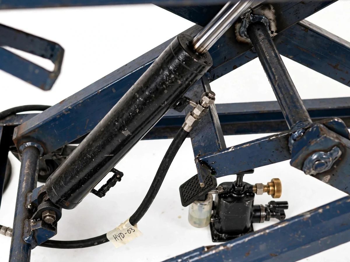
- The operator pumps the foot-pedal treadle; each stroke pushes a small volume of jack oil through the high-pressure hose into the welded hydraulic cylinder.
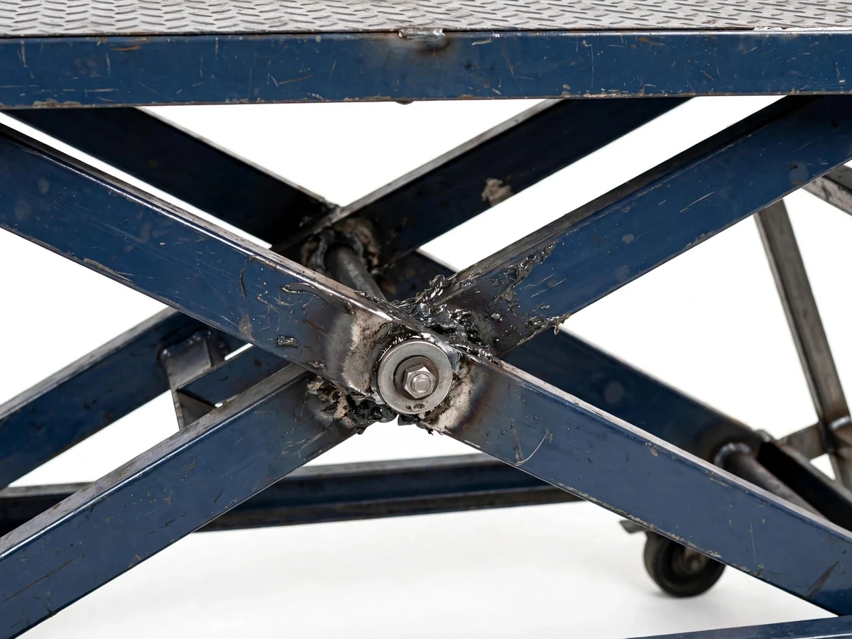
- Oil pressure extends the piston rod, which pushes against the scissor linkage; the flat-bar arms rotate about their pivot pins, the X closes, and the top frame and platform rise a few millimetres per stroke.
- At the working height the operator swings the mechanical safety prop bar into its notch, so the raised load is carried by the steel bar and not by oil pressure.
- To lower, the operator first releases the prop bar, then cracks open the needle valve by hand; oil meters back to the reservoir at a controlled rate and the platform descends smoothly.
- Before first real use, the student runs the documented proof-load procedure: the platform is loaded in steps up to the 200 kg design target while lift height, drift and weld behaviour are observed and recorded.
- Air in the circuit is bled at the cylinder port during commissioning so the pedal strokes stay firm and the motion stays predictable.
Design calculation (shown as calculation, not a measured claim): Design load 200 kg → weight force 200 × 9.81 = 1962 N. Applying a scissor-linkage force factor of 1.5 (design assumption), the cylinder must push approximately 2943 N. Selected cylinder bore 40 mm → piston area π/4 × 40² = 1256.6 mm². Required pressure = 2943 ÷ 1256.6 ≈ 2.34 N/mm² ≈ 23.4 bar. The relief valve is therefore set at approximately 30 bar (design setting). Cylinder stroke 200 mm maps to approximately 450 mm of platform travel through the scissor geometry (design target). These figures are the design basis the student verifies with the proof-load procedure; they are not claimed as tested results.
Tech stack:
- Mild steel fabrication (flat bar, square tube, plate)
- Welded hydraulic cylinder (40 mm bore)
- Foot-pedal hydraulic pump with reservoir
- High-pressure hose · fittings
- Needle valve lowering control
- Chequered steel platform plate
- Caster wheels with brakes
- Mechanical safety prop bar
| Parameter | Value |
|---|---|
| Platform size | 600 × 900 mm chequered steel plate (design) |
| Design load | 200 kg (design target — verified by the buyer-run proof-load procedure, not claimed as tested) |
| Platform travel | Approximately 450 mm (design target) |
| Lowered / raised height | Approximately 250 mm / 700 mm (design targets) |
| Cylinder | Welded hydraulic cylinder, 40 mm bore × 200 mm stroke (design selection) |
| Working pressure | Approximately 23.4 bar at the design load (design calculation) |
| Relief valve setting | Approximately 30 bar (design setting) |
| Pump | Foot-pedal hydraulic pump with integral oil reservoir |
| Lowering | Hand-operated needle valve (design) |
| Frame | Mild-steel flat-bar scissor arms on pivot pins, welded base and top frames |
| Casters | 4 nos., with brakes (design selection) |
| Safety | Mechanical safety prop bar for the raised position |
| Oil | ISO VG 32/46 hydraulic jack oil (design specification) |
| Power requirement | None — human-powered hydraulics |
Project features
- [Foot-pedal hydraulic pump] A treadle-style foot pump with an integral oil reservoir builds system pressure by hand-pumping, so the table lifts loads with no electricity, motor or external power source — ideal for workshops without power points.
- [Single-stage scissor linkage] Two pairs of mild-steel flat-bar arms cross in an X and rotate about central pivot pins, converting the cylinder's short stroke into approximately 450 mm of platform travel with fine, controlled motion.
- [Welded hydraulic cylinder] A black welded hydraulic cylinder with a chrome piston rod is pinned between the base frame and the scissor linkage; the piston force is sized from the design calculation, not guessed.
- [Needle-valve lowering control] A hand-operated needle valve meters oil back to the reservoir, so the platform descends slowly and predictably instead of dropping.
- [Mechanical safety prop bar] Once raised, a steel prop bar swings into a support notch and carries the load mechanically — the table never relies on trapped oil pressure alone while anyone works near it.
- [Mobile caster base with brakes] Four caster wheels make the table easy to roll into position; brakes on the casters lock it solid before any lifting begins.
- [Chequered anti-slip platform] A 600×900 mm diamond-pattern steel plate gives the load a non-slip working surface and resists the dents and scratches of real workshop use.
- [Design-calculation documentation] The full design calculation — load force, cylinder bore from F = P·A, scissor linkage factor, relief-valve setting, stroke-versus-lift geometry — is documented step by step for the report and the viva.
What is included
- Working prototype: fabricated and assembled scissor lift table, commissioned and bled
- Design calculation sheet (load force, cylinder bore, linkage factor, relief setting, stroke-versus-lift geometry)
- Fabrication drawings / general-arrangement sketch with member sizes
- Bill of materials with sourcing notes for the cylinder, pump, hose and fittings
- Operating and maintenance procedure (including the air-bleeding step and the proof-load procedure)
- Project report PDF (background, mechanism theory, hydraulics basics, design calculations, fabrication method, results of the proof-load run)
- PPT presentation for final review
- Viva Q&A preparation document (scissor mechanism, Pascal's law, cylinder sizing, safety)
Limitations & prerequisites
- The 200 kg capacity is a DESIGN TARGET from calculation — it is not a load-tested rating. The build ships with a documented buyer-run proof-load procedure; the verified figure is the one the student measures.
- The table must stand on a flat, level, hard floor (concrete is assumed). Sloping, soft or uneven ground makes the caster base unstable — this is not permitted in the operating procedure.
- No side loading: loads must be centred on the platform. Lateral forces bend the scissor arms and can tip the table; pushing or dragging loads across the platform is not allowed.
- The table must never be used to lift people. It is an academic prototype, not a manlift and not safety-certified.
- The safety prop bar must be engaged before anyone reaches near or under the raised platform — trapped oil pressure alone is never trusted.
- Jack oil (ISO VG 32/46) needs periodic top-up, and hoses and fittings must be inspected for weeps before each use; a leaking hose lets the platform descend unexpectedly.
- Pinch points exist at the scissor pivots, roller tracks and the prop-bar notch — hands and fingers must stay clear during raising and lowering.
- Fabrication quality is student-shop standard (arc welding, painted finish), not an industrial finish; the table is a working teaching build, and heavy daily commercial use will wear the pins and paint faster than a factory unit.
Frequently Asked Questions
Does the table need electricity?
No. The foot-pedal pump is entirely human-powered hydraulics — oil pressure comes from the operator's foot, so the table works anywhere with a flat floor.
Is the 200 kg load capacity tested?
The 200 kg figure is a design target from the documented calculation, stated honestly. The build includes a step-by-step proof-load procedure the student performs and records; that run — not the calculation alone — is what the report presents as the verified figure.
How is the load kept up while someone works on it?
A mechanical steel prop bar swings into a support notch once the platform is raised. The load then rests on the bar, not on oil pressure, so a slow leak cannot drop the platform on anyone.
What maintenance does it need?
Top up the jack oil (ISO VG 32/46) as needed, inspect hoses and fittings for weeps before each use, keep the pivot pins greased, and check the caster brakes and prop bar for wear — the maintenance procedure is included.
Is this project suitable for a final-year project?
Yes — for Mechanical Engineering, Production and Production/Industrial programmes. It demonstrates scissor-mechanism kinematics, hydraulic cylinder sizing from Pascal's law, fabrication and welding, and honest engineering documentation including a design-versus-verification story that examiners value.
Can it be customized?
Realistic options: a larger platform, a two-stage scissor for more height, an electric-hydraulic power pack instead of the foot pump, or a different design load — each changes the cylinder sizing and the documentation, and is quoted separately.
Components & software requirements
- Mild steel fabrication (flat bar, square tube, plate)
- Welded hydraulic cylinder (40 mm bore)
- Foot-pedal hydraulic pump with reservoir
- High-pressure hose · fittings
- Needle valve lowering control
- Chequered steel platform plate
- Caster wheels with brakes
- Mechanical safety prop bar
Delivery information
Built-to-order project. Delivery timeline is shared after order confirmation based on current queue.
Support terms
Complete documentation, setup guide, and viva preparation included. Support for setup and explanation provided.
Download free synopsis (PDF)
Enter your name and email — the synopsis PDF downloads immediately. We may send occasional project updates; no spam, unsubscribe anytime.