
More project photos (2)
The problem
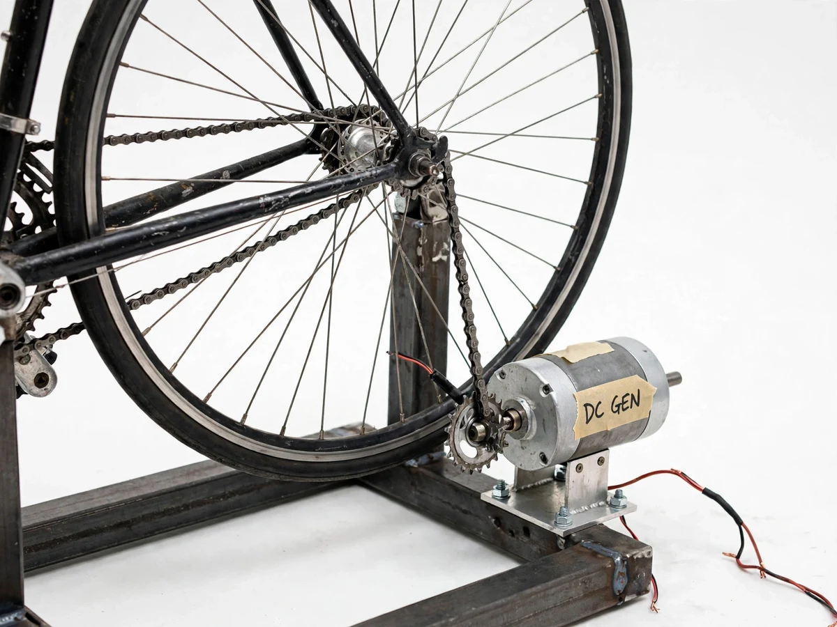
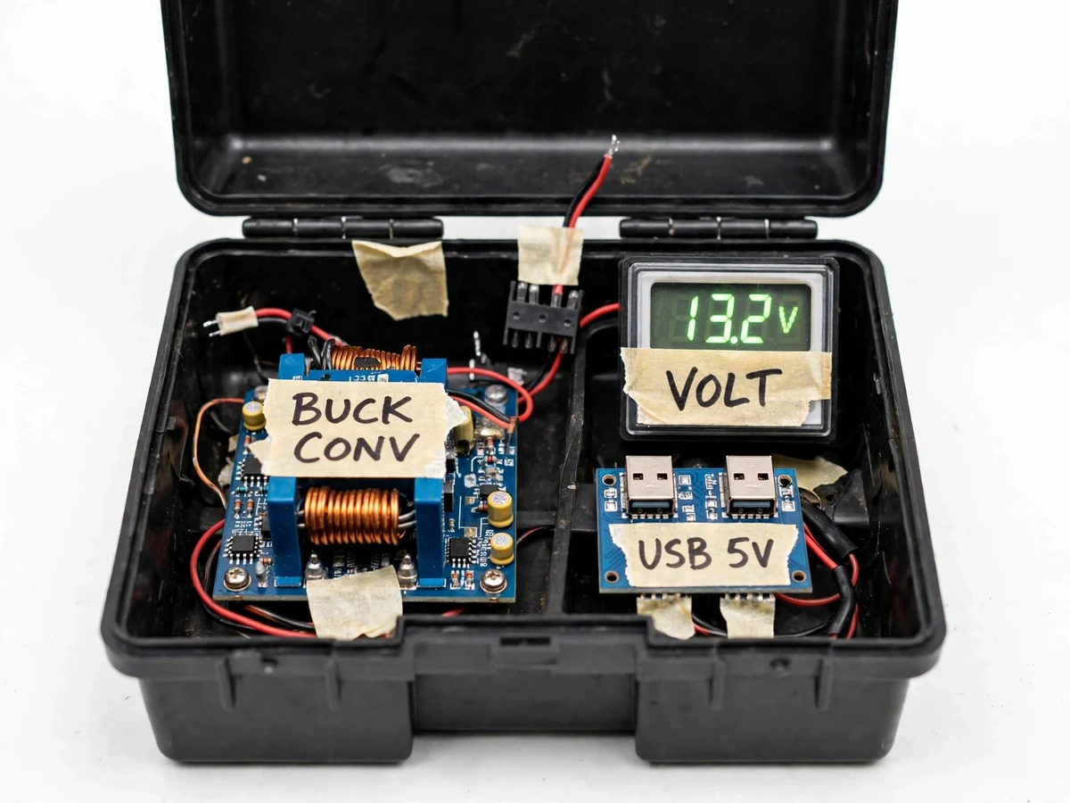
A bicycle is one of the most efficient human-power machines ever built, yet almost all of a rider's effort normally disappears as heat and motion. This project captures that effort: the bicycle is clamped into a welded steel trainer stand, and the pedal crank drives a permanent-magnet DC generator through a chain-and-sprocket step-up drive. Because generator voltage swings wildly with pedaling speed, a buck converter and USB regulator stage tame it into a stable 5V USB output that can charge phones, power banks and small devices. A digital panel voltmeter on the control box shows the generator-side voltage in real time, so the rider learns to hold the steady cadence that keeps charging alive. Nothing about the output is exaggerated — the page, report and viva notes all state the expected 40–60 W sustained range as a design target, and explain exactly where the rider's leg power goes in the chain, bearings and conversion stages.
Rider pedals the bicycle clamped in the trainer stand
Follow the working sequence
How it works
- The rider pedals the bicycle clamped in the trainer stand; the crank and chain drive a step-up sprocket on the generator shaft.
- The spinning permanent-magnet DC generator produces raw DC in the 12–24 V design-target range, rising and falling with pedaling speed.
- Raw output passes through the fuse and protection stage, then into the buck converter, which steps it down to a stable 5 V.
- The USB regulator board delivers the regulated 5 V to USB-A ports, charging phones, power banks and small 5 V devices.
- The panel voltmeter shows generator-side voltage at all times, so the rider adjusts cadence to stay inside the charging band.
- With the optional 12 V buffer battery fitted, surplus energy is stored while pedaling and USB charging continues briefly after pedaling stops.
Tech stack:
- Bicycle with chain-and-sprocket drive (step-up ratio, approximately 1:5 design target)
- Permanent-magnet DC motor used as generator
- Buck converter module (DC–DC step-down)
- USB regulator board, 5 V output
- Digital panel voltmeter
- Lead-acid battery, 12 V (optional customization)
- Fuse and over-voltage protection circuitry
- Welded steel trainer stand
| Parameter | Value |
|---|---|
| Power source | Human pedaling via bicycle crank |
| Drive | Chain and sprocket, step-up to generator shaft (approximately 1:5 ratio, design target) |
| Generator | Permanent-magnet DC motor used as generator |
| Generator output | 12–24 V DC (design target; varies with cadence) |
| USB output | Regulated 5 V DC, up to 2 A (regulator rating, design target) |
| Sustained electrical output | Approximately 40–60 W at comfortable pedaling (expected, design target — not a measured claim) |
| Voltage display | Digital panel voltmeter on generator side |
| Buffer storage | 12 V lead-acid battery (optional customization) |
| Frame | Welded steel trainer stand, fits a standard bicycle |
| Protection | Fuse, reverse-polarity and over-voltage clamping (design target values) |
Project features
- [Chain-drive power transfer] The pedal crank drives the generator shaft through a bicycle chain and a step-up sprocket pair, so a comfortable pedaling cadence spins the generator fast enough to reach its useful voltage band.
- [Permanent-magnet DC generator] A permanent-magnet DC motor run in reverse as a generator converts crank torque into raw DC (12–24 V design target) with no external power needed to start generation.
- [Regulated 5V USB charging] A buck converter steps the swinging generator output down to a stable 5V, and a USB regulator board presents it on USB-A ports — phones charge safely even as pedaling speed varies.
- [Panel voltmeter feedback] A digital voltmeter on the control box displays generator-side voltage continuously, giving the rider a live target to hold for uninterrupted charging.
- [Over-voltage and overload protection] A fuse plus reverse-polarity and over-voltage clamping protect the USB port from spikes when pedaling surges or a device is unplugged abruptly.
- [Optional 12V buffer battery] As an optional customization, a 12V lead-acid battery stores surplus energy while pedaling so USB charging continues for a short period after the rider stops.
- [Rigid steel trainer stand] A welded steel stand clamps a standard bicycle upright and holds the generator bracket in alignment, keeping the whole rig stable during hard pedaling.
What is included
- Working pedal-power generator prototype: bicycle on trainer stand, chain drive, DC generator, control box with buck converter, USB board and panel voltmeter
- Component list with ratings and sourcing notes
- Wiring diagram of the generator, protection, converter and USB stages
- Setup and pedaling-test instructions, including how to find the steady-cadence charging band
- Project report PDF (background, drive-ratio and power calculations, methodology, expected results)
- PPT presentation for final review
- Viva Q&A preparation document (energy conversion, mechanical drive, voltage regulation, protection, losses)
Limitations & prerequisites
- Output depends entirely on the rider — the 40–60 W range is an expected design target, and output falls to zero the moment pedaling stops unless the optional buffer battery is fitted.
- USB charging needs a minimum generator voltage; slow or uneven pedaling can drop below the regulator's dropout threshold and pause charging.
- Only 5 V USB devices are supported — no laptops and no mains appliances; this is a small-device charger, not household power.
- Chain, bearing and generator losses mean electrical output is a fraction of the rider's leg power; efficiency is component-dependent and stated as expected, not measured.
- The prototype is not weatherproof and not certified for outdoor public use; it is built for indoor demonstration and lab evaluation.
Frequently Asked Questions
How much electricity does pedaling actually produce?
For an average rider at a comfortable cadence, expect roughly 40–60 W of sustained electrical output — stated as a design target, not a measured claim. Fitter riders produce more in bursts, but nobody sustains burst power for long. The report walks through where the energy goes: chain friction, bearing drag, generator losses and conversion losses each take their share.
Is this project suitable for a final-year project?
Yes — for Mechanical, Electrical and Electronics programs. It demonstrates mechanical power transmission (chain drive, step-up ratios), electromagnetic energy conversion, DC–DC regulation and protection design. The calculations chapter — drive ratios, expected output and loss budgeting — gives examiners concrete engineering to question, and the viva discussion on losses and efficiency is genuinely strong material.
What devices can it charge?
Any 5 V USB device: phones, power banks, Bluetooth speakers, small LED lamps and similar low-power gadgets. It cannot charge laptops or run mains appliances — the USB stage is current-limited by design, and the page states this plainly so nobody buys it expecting more.
Does charging continue when I stop pedaling?
Not in the base build — generation stops with the pedals. The optional 12 V lead-acid buffer battery stores surplus energy while you pedal and keeps the USB ports alive for a short period afterwards; it is a customization, not part of the base price.
Does pedaling speed really matter?
Yes. The generator's voltage rises and falls with cadence, and the buck converter needs the input above its dropout threshold to hold a steady 5 V. Pedal too slowly and charging pauses; the panel voltmeter exists precisely so the rider can see the voltage and settle into the right rhythm.
Can this power a house or run home appliances?
No, and the listing makes no such claim. Human legs sustain tens of watts, while even a single room's lighting and fans need hundreds. This project is an honest demonstrator of human-power harvesting for small devices, plus a solid study of drives, generators and regulation. Suitable for B.E./B.Tech final-year projects in Mechanical, Electrical and Electronics Engineering.
Components & software requirements
- Bicycle with chain-and-sprocket drive (step-up ratio, approximately 1:5 design target)
- Permanent-magnet DC motor used as generator
- Buck converter module (DC–DC step-down)
- USB regulator board, 5 V output
- Digital panel voltmeter
- Lead-acid battery, 12 V (optional customization)
- Fuse and over-voltage protection circuitry
- Welded steel trainer stand
Delivery information
Built-to-order project. Delivery timeline is shared after order confirmation based on current queue.
Support terms
Complete documentation, setup guide, and viva preparation included. Support for setup and explanation provided.
Download free synopsis (PDF)
Enter your name and email — the synopsis PDF downloads immediately. We may send occasional project updates; no spam, unsubscribe anytime.