
More project photos (3)

The problem
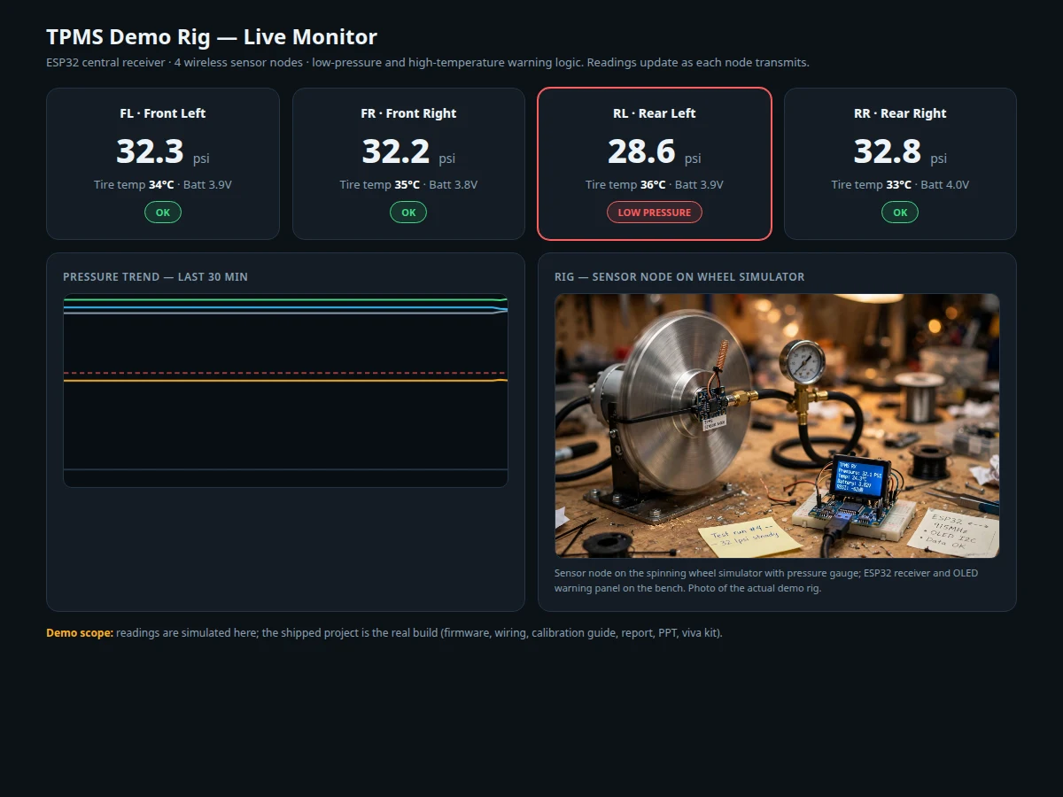
Under-inflated tires wear faster, consume more fuel and are a genuine safety risk, yet most drivers only check pressure occasionally. Modern cars solve this with TPMS — battery-powered sensor nodes inside each wheel that report pressure and temperature wirelessly to the car. Reproducing that full wireless signal chain on a bench is exactly what this rig does: four wheel-simulator discs carry sensor nodes (pressure sensor, temperature sensor, Arduino Nano and RF module), each spinning freely to demonstrate rotation-stable sensing. An ESP32 receiver with an OLED display acts as the "dashboard cluster," lighting warning icons when a node reports low pressure or high temperature, while a serial/web dashboard logs every reading with per-wheel trend charts. The build uses custom sensor nodes rather than hacking commercial TPMS units (whose RF protocols are proprietary and undocumented), which makes the entire wireless protocol inspectable for the report and viva.
Four Arduino Nano nodes sampling pressure and temperature on the spinning wheel simulators.
Follow the working sequence
How it works
- Each sensor node samples its pressure and temperature sensors and packages the readings with node ID and battery voltage.
- The packet is transmitted over the RF link; the ESP32 receiver listens continuously and decodes incoming frames by node ID.
- The receiver compares each wheel's pressure against the configured low-pressure threshold and temperature against the high-temperature threshold.
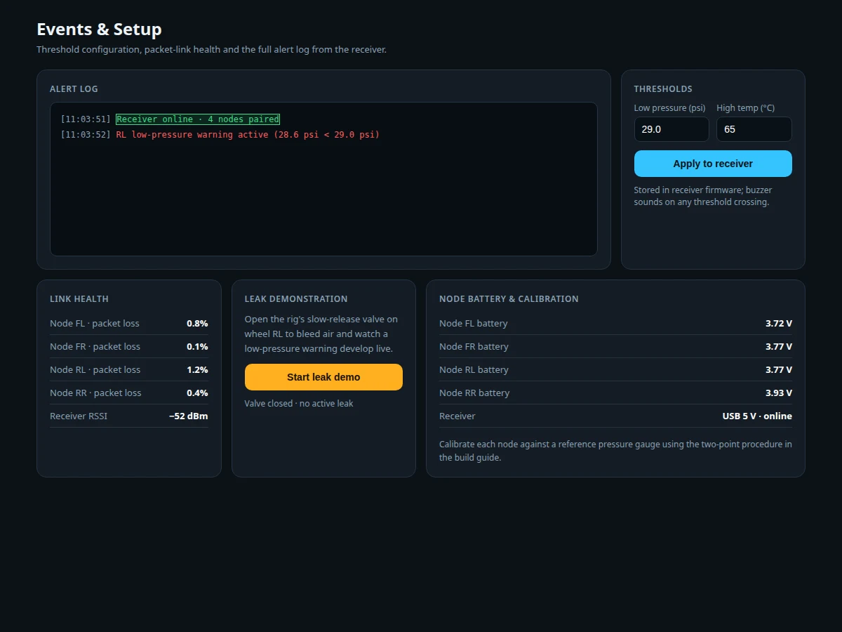
- On a threshold crossing, the OLED panel lights the corresponding wheel warning and the buzzer sounds; the event is time-stamped in the alert log.
- All readings stream to the dashboard: per-wheel cards show current values, charts show trends, and packet-loss counters show link quality.
- The leak-demo valve on a wheel simulator bleeds air slowly, letting students watch a low-pressure warning develop live on the dashboard.
Tech stack:
- Arduino Nano sensor nodes (4×), ESP32 DevKit receiver
- Pressure sensor modules (analog/I2C), temperature sensors
- RF modules (e.g. NRF24L01+ with PA/LNA for range)
- 0.96" OLED display + buzzer for the warning panel
- Wheel-simulator discs with bearings, leak-demo bleed valve
- Serial/web dashboard (HTML/CSS/JS, live charts)
| Parameter | Value |
|---|---|
| Sensor nodes | 4× Arduino Nano + pressure/temperature sensors + RF module |
| Receiver | ESP32 DevKit, OLED warning panel + buzzer |
| Wireless | RF link; design target reliable reception within a 10 m lab area |
| Thresholds | Low-pressure and high-temperature, configurable in firmware |
| Calibration | Documented procedure against a reference pressure gauge |
| Power | Node batteries; receiver on USB 5 V |
| Dashboard | Per-wheel cards, trend charts, alert log, packet-loss indicators |
| Rig | 4 spinning wheel simulators with bearings + slow-release demo valve |
Project features
- [Four wireless sensor nodes] Each node carries a pressure sensor, temperature sensor, Arduino Nano and RF module, mounted on a spinning wheel simulator to prove sensing works under rotation.
- [ESP32 central receiver] Decodes all four node packets, runs the warning logic, and drives an OLED panel showing per-wheel pressure and temperature.
- [Warning logic] Low-pressure and high-temperature thresholds are configurable; the panel lights wheel-specific warnings and a buzzer sounds on threshold crossing.
- [Live dashboard] Four-wheel pressure cards, per-wheel temperature trend charts, an alert log and a signal-quality (packet-loss) indicator for each node.
- [Battery health monitoring] Nodes report battery voltage with each packet; the dashboard flags nodes approaching low-battery.
- [Calibration procedure] A documented check against a reference pressure gauge lets the buyer calibrate each node to their own rig.
- [Leak demonstration mode] A controlled slow-release valve on the rig lets the dashboard show a developing low-pressure event over time.
- [Complete build docs] Rig drawings, wiring diagrams, firmware and calibration guide.
What is included
- Complete sensor-node and receiver firmware (packet protocol, warning logic, thresholds)
- Rig fabrication drawings and parts list (wheel simulators, mounting, valve)
- Wiring diagrams for nodes and receiver
- Calibration guide (reference-gauge procedure per node)
- Web dashboard (live cards, charts, alert log)
- Project report PDF (TPMS background, RF protocol design, evaluation method)
- PPT presentation for final review
- Viva Q&A preparation document (TPMS principles, RF, calibration, warnings)
Limitations & prerequisites
- This is a bench demonstration rig, not a road-certified TPMS. It is not sealed, vibration-rated or temperature-rated for real vehicle use, and must never be fitted to a road vehicle.
- Pressure accuracy follows the sensor module's datasheet and the quality of the calibration against the reference gauge — no certified accuracy is claimed.
- The custom RF protocol is simpler than commercial TPMS protocols; it does not include the encryption or pairing schemes of production vehicles.
- Wireless range is lab-scale; the design target is reliable reception within about 10 m, and metal structures between node and receiver degrade the link.
- Sensor-node batteries need periodic recharging/replacement; the dashboard monitors and flags low battery, but the rig does not power nodes wirelessly.
Frequently Asked Questions
Which controller is used?
Arduino Nano on each of the four sensor nodes and an ESP32 as the central receiver. The ESP32 runs the warning logic, drives the OLED panel and feeds the dashboard.
Are these real TPMS sensors?
No — commercial TPMS sensors use proprietary, undocumented RF protocols that cannot be interfaced cleanly in a student build. This project uses custom sensor nodes with standard pressure/temperature modules and an open RF protocol, so the whole signal chain is inspectable and explainable.
Does it work on a real car?
No. This is a bench rig for demonstrating the TPMS signal chain. It is not sealed, vibration-proof or certified for vehicle use.
How accurate is the pressure reading?
Accuracy follows the sensor module's datasheet after you run the documented calibration against a reference gauge. The report states this calibration dependence explicitly.
Can it work without a PC?
Yes — the ESP32 receiver with its OLED warning panel and buzzer works standalone. The PC dashboard adds logging and charts.
Is this project suitable for a final-year project?
Yes — for Mechanical, Mechatronics and Automotive programs. It demonstrates sensors, wireless telemetry, threshold-based safety logic, calibration discipline and a working mechanical rig, all strong viva material. Suitable for B.E./B.Tech final-year projects in Mechanical, Mechatronics and Automotive.
Components & software requirements
- Arduino Nano sensor nodes (4×), ESP32 DevKit receiver
- Pressure sensor modules (analog/I2C), temperature sensors
- RF modules (e.g. NRF24L01+ with PA/LNA for range)
- 0.96" OLED display + buzzer for the warning panel
- Wheel-simulator discs with bearings, leak-demo bleed valve
- Serial/web dashboard (HTML/CSS/JS, live charts)
Delivery information
Built-to-order project. Delivery timeline is shared after order confirmation based on current queue.
Support terms
Complete documentation, setup guide, and viva preparation included. Support for setup and explanation provided.
Download free synopsis (PDF)
Enter your name and WhatsApp number — the synopsis PDF downloads immediately. We may send occasional project updates on WhatsApp; no spam.