
More project photos (2)
The problem
Anti-lock braking is one of the most widely deployed safety systems in automobiles, yet in the classroom it stays an equation: slip ratio curves, friction circles, and a block diagram of "the controller." The physical behavior — pressure modulating many times per second while a wheel hovers on the edge of lockup — is never seen. Commercial ABS test rigs cost lakhs and are out of reach for student labs. This project closes that gap with a bench-scale rig: a DC-motor-driven wheel with a Hall-effect speed sensor on a tone ring, an Arduino that computes slip against a reference speed, and a solenoid brake actuator the controller pulses to keep slip near the 15% design target. Students watch modulation happen live — on the rig's LCD, in the event log, and on the dashboard's wheel-speed traces — and run the classic comparison test: ABS-on stop versus a locked-wheel stop. Because the slip target, modulation rate and reference speed are all configurable in firmware, the rig doubles as a control-theory teaching platform.
How it works
- The DC drive motor spins the wheel to the set reference speed (e.g. 850 rpm); the tone ring rotates with it.
- Hall-effect sensors count tone-ring teeth 60 times per revolution, giving precise wheel rpm at the Arduino.
- The firmware computes slip as (reference speed − wheel speed) / reference speed, continuously.
- When you press the pedal, the Arduino drives the solenoid brake; when slip exceeds the 20% threshold, it releases pressure for ~60 ms, then re-applies.
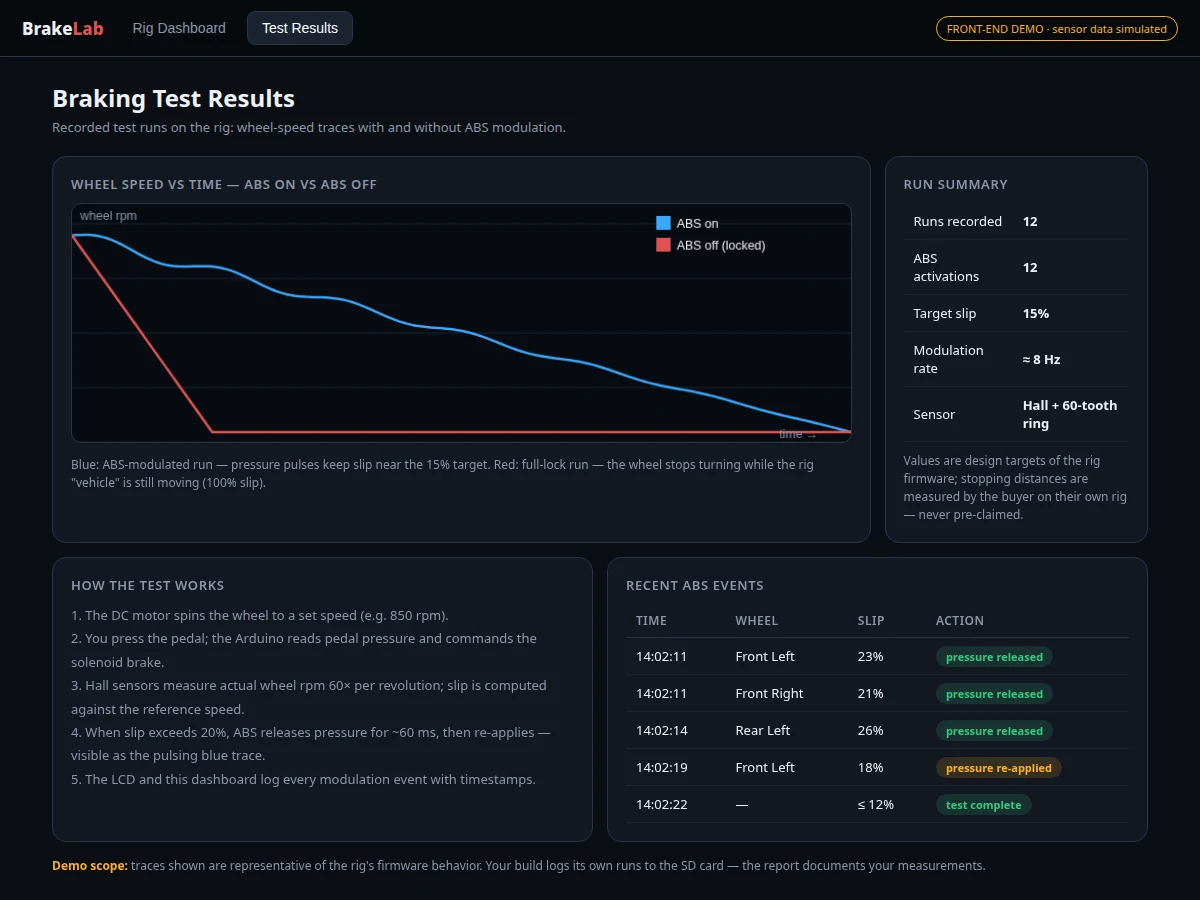
- The pulsing keeps slip hovering near the 15% target instead of the wheel locking — visible as the pulsing blue trace on the dashboard.
- Every modulation event is timestamped to the event log, the LCD and the SD card; the comparison mode records ABS-on and ABS-off traces for the report.
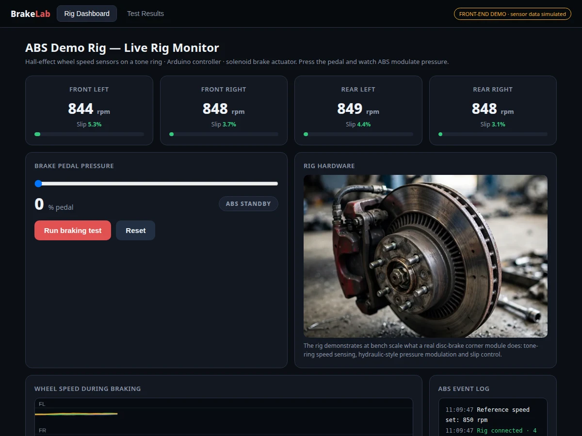
- The dashboard renders live rpm, slip bars and the traces; the report's test procedure documents how the buyer measures modulation rate and slip behavior on their own rig.
Tech stack:
- Arduino Uno (ATmega328P, Arduino-core firmware with commented slip-control loop)
- Hall-effect wheel speed sensors + 60-tooth tone ring
- DC drive motor with speed controller (reference-speed source)
- Solenoid brake actuator + caliper assembly
- 16x2 LCD (I2C) for on-rig readout; SD card module for test logging
- USB serial telemetry to the dashboard web app
- Single-file HTML/CSS/JS dashboard (live monitor, test-results views)
| Parameter | Value |
|---|---|
| Controller | Arduino Uno (ATmega328P), Arduino-core firmware |
| Speed sensing | Hall-effect sensors, 60-tooth tone ring (60 pulses/rev) |
| Wheels | 1 driven test wheel shown; firmware supports 4 sensor channels |
| Reference speed | Configurable; 850 rpm default test speed |
| Slip target | 15% (configurable); release threshold ~20% |
| Modulation rate | ~8 Hz design target (pressure release ~60 ms) |
| Brake actuator | Solenoid-driven caliper |
| On-rig display | 16x2 I2C LCD (live slip, ABS state) |
| Logging | SD card: per-test rpm traces + event timestamps |
| Dashboard | USB serial; live rpm/slip, event log, ABS-on vs locked traces |
Project features
- [Four-wheel speed sensing] Hall-effect sensors read a 60-tooth tone ring on each driven wheel, giving high-resolution rpm — the same principle real ABS tone rings use, at bench scale.
- [Slip-ratio control loop] The Arduino compares wheel rpm against the reference speed, computes slip continuously, and releases/re-applies brake pressure to hold slip near the configurable 15% design target.
- [Solenoid brake actuator] A solenoid-driven brake caliper provides the fast on/off pressure modulation (~8 Hz design target) that stands in for hydraulic ABS valves.
- [Live rig dashboard] The companion dashboard streams per-wheel rpm, slip bars, brake-pedal pressure, ABS state and a timestamped modulation event log over USB serial.
- [ABS-on vs locked test mode] Record wheel-speed traces with ABS enabled and disabled; the comparison chart shows the modulated stop against the locked-wheel slide — the centerpiece viva demonstration.
- [Configurable firmware] Slip target, modulation rate, reference speed and sensor calibration are all constants in commented firmware, so examiners can probe control-theory understanding live.
- [LCD + SD logging] A 16x2 LCD shows live slip on the rig itself; every braking test logs rpm traces to the SD card for the report's graphs.
- [Complete build docs] Wiring diagram, tone-ring mounting guide, sensor-gap calibration procedure, and firmware with commented control logic.
What is included
- Complete Arduino firmware (speed sensing, slip computation, modulation control, logging)
- Rig hardware build guide (frame, motor mount, tone-ring fitting, brake assembly)
- Wiring diagram and sensor-gap calibration procedure
- Live dashboard web app (rig monitor + test-results views)
- Project report PDF (background, control design, test procedure, evaluation method)
- PPT presentation for final review
- Viva Q&A preparation document (slip ratio, ABS theory, Hall sensors, control loops, calibration)
- Setup guide (assembly, first spin-up, first braking test)
Limitations & prerequisites
- This is a bench-scale demonstrator, not a vehicle braking system: it models one wheel's dynamics with a motor as the "vehicle" — stopping distances are not comparable to real cars, and the report states this explicitly.
- The solenoid actuator stands in for hydraulic valves; pressure modulation is on/off pulsing rather than proportional hydraulic control.
- Slip and modulation figures are design targets and the buyer's own measurements — the report documents the measurement procedure, and no stopping performance is pre-claimed.
- Sensor accuracy depends on correct tone-ring gap setting; the calibration procedure must be run during assembly or rpm readings drift.
- The rig needs a stable bench power supply for the motor and solenoid; brownouts during braking tests corrupt the traces.
Frequently Asked Questions
How does the rig compute slip?
Each Hall sensor counts the 60-tooth tone ring's pulses to get wheel rpm. The Arduino compares this against the reference speed (the motor's set speed, standing in for vehicle speed) and computes slip = (reference − wheel) / reference, continuously, for every wheel channel.
What does the ABS control actually do?
When braking and slip exceeds ~20%, the firmware releases the solenoid brake for about 60 ms, then re-applies it. This pulsing — at a design target of ~8 Hz — keeps slip hovering near the 15% target instead of the wheel locking at 100% slip.
What is the locked-wheel comparison test?
The firmware can disable modulation so the brake locks the wheel fully. The dashboard records both traces: the ABS-on trace shows pulsed deceleration, the locked trace shows rpm dropping to zero while the "vehicle" (motor reference) is still moving — the classic viva demonstration.
How accurate are the wheel speed sensors?
The 60-tooth tone ring gives 60 pulses per revolution, so at 850 rpm the sensor delivers about 850 pulses per second — plenty of resolution for the control loop. Accuracy depends on the sensor-gap calibration done during assembly.
Can the slip target and modulation rate be changed?
Yes — both are constants in the commented firmware, along with reference speed and thresholds. Examiners can ask you to change the target and predict what happens, which makes it strong control-theory viva material.
Is this project suitable for a final-year project?
Yes — for Mechanical, Mechatronics and Automotive programs. It demonstrates real-time sensing, closed-loop slip control, actuator interfacing, data logging and experimental comparison, all strong viva material. Suitable for B.E./B.Tech final-year projects in Mechanical, Mechatronics and Automotive engineering.
Components & software requirements
- Arduino Uno (ATmega328P, Arduino-core firmware with commented slip-control loop)
- Hall-effect wheel speed sensors + 60-tooth tone ring
- DC drive motor with speed controller (reference-speed source)
- Solenoid brake actuator + caliper assembly
- 16x2 LCD (I2C) for on-rig readout; SD card module for test logging
- USB serial telemetry to the dashboard web app
- Single-file HTML/CSS/JS dashboard (live monitor, test-results views)
Delivery information
Built-to-order project. Delivery timeline is shared after order confirmation based on current queue.
Support terms
Complete documentation, setup guide, and viva preparation included. Support for setup and explanation provided.