
More project photos (2)
The problem
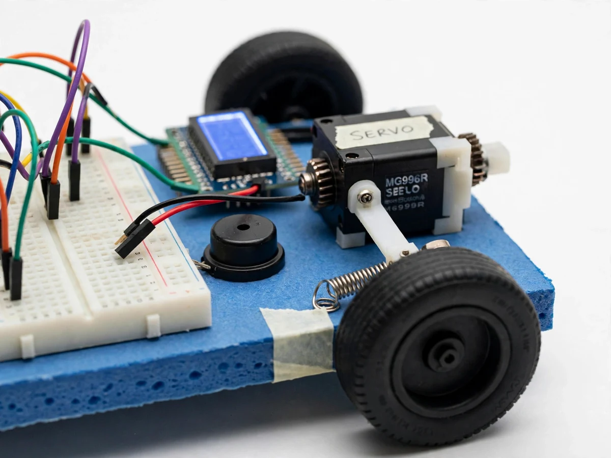
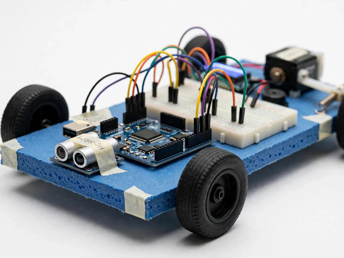
Rear-end collisions often happen because a driver reacts too slowly: a moment of distraction adds the driver's reaction time to the braking distance, and at speed that extra delay is the difference between a near-miss and an impact. Modern cars answer with automatic emergency braking — radar and camera systems that sense an obstacle and brake without the driver. The core ideas — distance sensing, threshold comparison, actuator-driven braking — are accessible at model scale with cheap components. This project demonstrates the full chain on a demo vehicle model: an HC-SR04 ultrasonic sensor at the nose measures the distance to obstacles ahead, an Arduino Uno compares each reading against a configurable braking threshold, and when the threshold is crossed the Arduino drives a servo actuator whose linkage presses a spring-return brake lever on the model car. A 16x2 LCD shows the live distance and the RUN/BRAKE state, and a buzzer warns in a caution band before braking engages. The build is a study of sensing, decision logic and mechatronic actuation — honest model engineering, not a claim about road-vehicle safety.
Emits a 40 kHz burst and returns an echo pulse whose width encodes distance.
Follow the working sequence
How it works
- At power-up the Arduino initializes the ultrasonic sensor, servo, LCD and buzzer; the model car starts in RUN state with the brake lever held released by its return spring.
- The Arduino sends a 10-microsecond trigger pulse to the HC-SR04, which emits an 8-pulse 40 kHz ultrasonic burst and returns an echo pulse whose width encodes the round-trip travel time.
- Firmware converts echo time to distance (distance in cm equals echo time in microseconds divided by 58 at room temperature) and updates the LCD with the live value every measurement cycle.
- Each reading is compared with the configured braking threshold; if the distance is below the threshold on consecutive confirmed readings, the state switches from RUN to BRAKE.
- In BRAKE state the Arduino rotates the servo, whose linkage arm presses the brake lever against the wheel/driveline and slows the model car to a stop; the LCD shows BRAKE and the buzzer pattern changes.
- Once the obstacle clears beyond a release distance (hysteresis built into the firmware), the servo returns, the lever springs back, and the car resumes RUN state for the next demonstration.
Tech stack:
- Arduino Uno (ATmega328P)
- HC-SR04 ultrasonic sensor
- MG996R-class servo motor
- 16x2 character LCD
- Piezo buzzer
- Embedded C (Arduino IDE)
- DC motor drive for model car
- Model chassis with linkage hardware
| Parameter | Value |
|---|---|
| Controller | Arduino Uno (ATmega328P, 5 V logic) |
| Sensor | HC-SR04 ultrasonic, 2–400 cm range (datasheet), 0.3 cm resolution (datasheet) |
| Sensor beam angle | Approximately 15 degrees (datasheet) |
| Braking threshold | Configurable, default 30 cm (user-set in firmware or trim pot) |
| Actuator | MG996R-class servo, 9.4 kg-cm at 4.8 V (datasheet) |
| Display | 16x2 character LCD showing distance in cm plus RUN/BRAKE state |
| Sense-to-actuate latency | Under 0.5 s (design target) |
| Vehicle | Approximately 1:10–1:16 scale demo model chassis (component-dependent) |
| Power | 5 V for logic; servo on a dedicated 5–6 V supply (recommended) |
| Connectivity | None required — fully autonomous on-board logic |
Project features
- [Front obstacle detection] An HC-SR04 ultrasonic sensor mounted at the car's nose continuously measures the distance to obstacles ahead, from 2 cm to 400 cm per the module datasheet, at up to roughly 20 measurements per second.
- [Threshold-based automatic braking] The Arduino compares every reading against a configurable braking threshold (default 30 cm). When the threshold is crossed on consecutive confirmed readings, braking engages with no human input involved.
- [Servo brake actuation] An MG996R-class servo motor drives a linkage arm that presses a spring-return metal brake lever against the model car's wheel or driveline, physically simulating pedal application. Braking force depends on linkage geometry and servo supply voltage.
- [Live distance and state display] A 16x2 LCD shows the current distance in centimetres and the system state (RUN / BRAKE), so the demonstration is readable by an audience without a laptop attached.
- [Caution-band warning buzzer] While the measured distance sits between the braking threshold and a wider warning distance, a piezo buzzer sounds — demonstrating staged alert-then-brake behaviour like real driver-assistance systems.
- [Configurable braking threshold] The trigger distance is set in firmware or via a trim potentiometer, letting the student demonstrate how stopping behaviour changes with tighter or looser settings during the viva.
- [Manual brake test button] A push-button forces one brake cycle on demand, so the actuator, linkage and lever can be demonstrated without placing an obstacle in front of the car.
What is included
- Working demo vehicle model with ultrasonic braking system
- Arduino firmware (embedded C) with threshold and hysteresis logic
- Wiring diagram and component list
- Threshold-setting and sensor-validation calibration procedure
- Project report PDF (background, working principle, calculations, methodology, results)
- PPT presentation for final review
- Viva Q&A preparation document (ultrasonics, Arduino timing, servo torque, linkage geometry)
Limitations & prerequisites
- The HC-SR04 cannot measure below 2 cm and reads unreliably off soft, angled or narrow surfaces; only obstacles inside its approximately 15-degree cone are detected (datasheet).
- This is a model-scale demonstration of sensing, decision and actuation logic — it is not a road-vehicle braking system, and no road-safety claim is made. Real automatic emergency braking uses radar/camera fusion and automotive-certified controllers.
- Stopping performance depends on the model car's weight, speed and wheel friction; no stopping distance is claimed as a measured specification.
- The threshold, servo linkage geometry and lever travel must be calibrated per build; the kit includes a buyer-run calibration procedure.
- Sensor range tops out at 400 cm per the datasheet, so the demo track must be sized to the braking distance of the model.
- Strong ambient ultrasonic noise can cause false echoes; firmware requires consecutive confirmed readings but cannot eliminate every false trigger.
Frequently Asked Questions
Is this project suitable for a final-year project?
Yes — for Mechanical and Electronics/Electrical Engineering students. It demonstrates ultrasonic distance sensing, embedded control logic, servo actuation and mechanical linkage design, and it makes a strong live demonstration for a final review.
Which controller and sensor are used, and why?
An Arduino Uno reads an HC-SR04 ultrasonic sensor (2–400 cm range, approximately 15-degree beam per datasheet). The combination is cheap, well documented, and the 5 V logic levels match directly with no level shifting needed.
How is the brake actually applied on the model?
A servo motor rotates a linkage arm that presses a spring-return metal brake lever against the wheel or driveline of the model car. When the obstacle clears, the servo releases and the spring returns the lever — the full press-and-release cycle is visible.
Does the system need internet or a phone app?
No. All logic runs on the Arduino — sensing, threshold comparison, actuation and display are fully autonomous on board, and the LCD shows the live distance and state.
Can the braking distance be changed?
Yes. The trigger threshold is configurable in firmware or via a trim potentiometer, so the student can demonstrate gentler or more aggressive braking during the viva.
Can this be fitted on a real car or bike?
Not as built — this is a model-scale concept demonstrator. Real vehicles need automotive-certified controllers, redundant sensors and homologated brake hardware; the project explains this boundary honestly in the report.
Components & software requirements
- Arduino Uno (ATmega328P)
- HC-SR04 ultrasonic sensor
- MG996R-class servo motor
- 16x2 character LCD
- Piezo buzzer
- Embedded C (Arduino IDE)
- DC motor drive for model car
- Model chassis with linkage hardware
Delivery information
Built-to-order project. Delivery timeline is shared after order confirmation based on current queue.
Support terms
Complete documentation, setup guide, and viva preparation included. Support for setup and explanation provided.
Download free synopsis (PDF)
Enter your name and email — the synopsis PDF downloads immediately. We may send occasional project updates; no spam, unsubscribe anytime.