
More project photos (2)
The problem
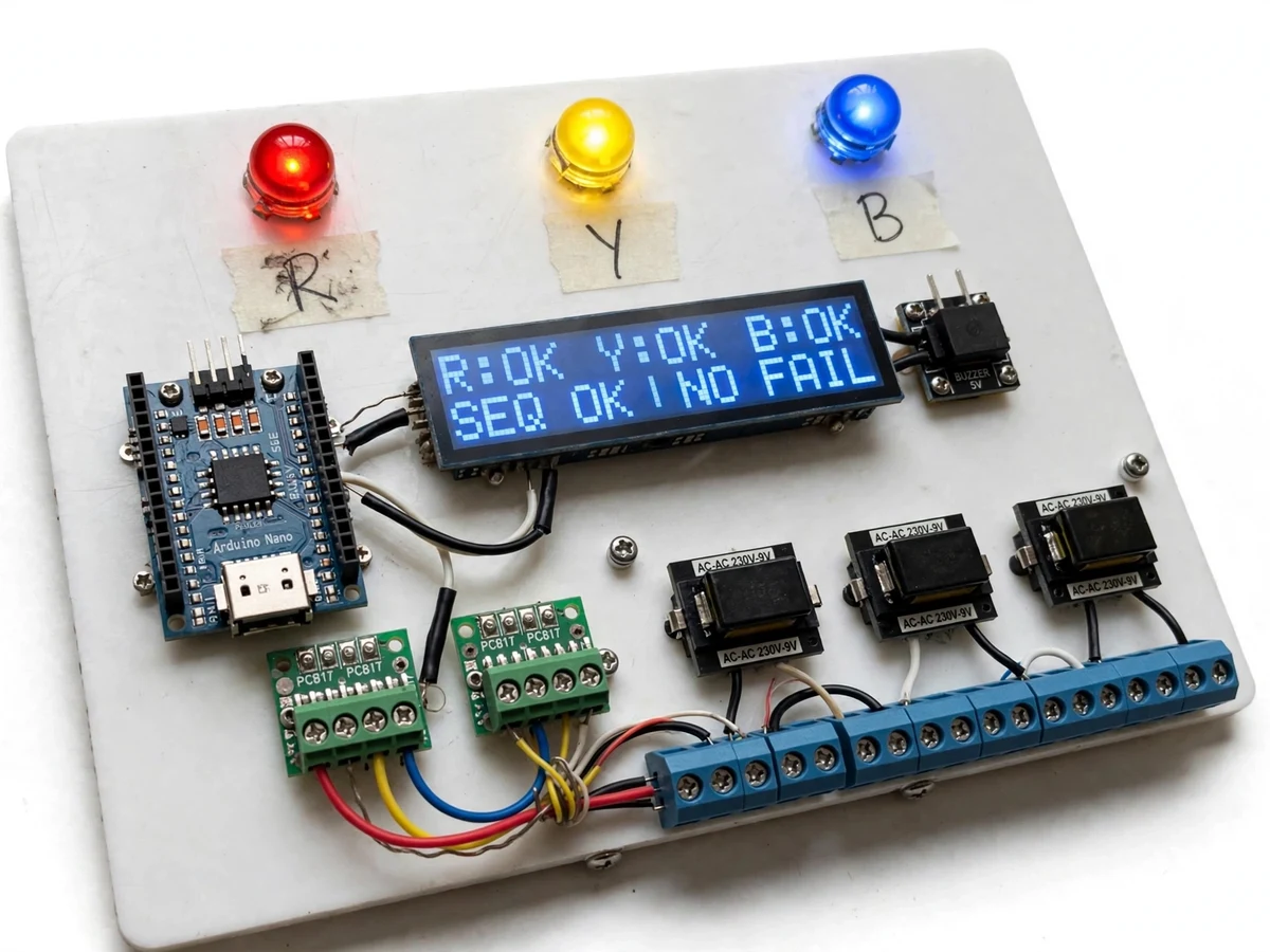
A lost phase or a reversed phase sequence can quietly destroy a three-phase motor: single-phasing overheats windings, and swapped phases run a pump or conveyor backwards. Factory panels include protection relays for this, but students rarely get to build and understand the detection logic themselves. This project fills that gap — a panel that watches three phases through transformer-isolated, optocoupler-buffered sensing and reports, in real time, whether each phase is present, whether the sequence is R-Y-B or reversed, and whether the phase voltage is inside the healthy band. A 16x2 LCD shows per-phase status, three LEDs give an at-a-glance view, and a buzzer sounds whenever a fault is declared. The design is deliberately built for a college lab: the mains side is stepped down through three small transformers and the controller side stays galvanically isolated, so the demo is safe to demonstrate without direct high-voltage probing. Everything is designed to be explainable in a viva — zero-crossing detection, phase-order logic and threshold comparison are all in the code and documented.
Operator reading the panel and silencing the buzzer.
Follow the working sequence
How it works
- The panel connects to a three-phase supply through three 230V-to-9V step-down transformers (one per phase), keeping the logic side galvanically isolated from the mains side.
- Each transformer secondary drives a PC817 optocoupler channel that emits a pulse at every zero crossing; the Arduino Nano timestamps these pulses with hardware interrupts.
- If pulses stop arriving from a phase for a set number of half-cycles (design target: 4 half-cycles, about 80 ms at 50 Hz), that phase is declared failed.
- The firmware compares the arrival order of the R, Y and B pulses — R-Y-B means correct sequence, R-B-Y means reversed — and reports SEQ OK or SEQ REV on the LCD.
- Each secondary is additionally scaled through a resistor divider into a 10-bit ADC channel; readings outside the buyer-calibrated band raise an under/over-voltage flag for that phase.
- Any declared fault lights the corresponding R/Y/B LED, updates the LCD, and sounds the buzzer; a push-button silences the buzzer, which re-arms on the next new fault.
Tech stack:
- ATmega328P · Arduino Nano (firmware in Arduino C)
- PC817 optocouplers · zero-crossing detection
- 3 × 230V-to-9V AC transformers · galvanic isolation
- 16x2 character LCD (HD44780)
- 5V active piezo buzzer
- R/Y/B panel LEDs · terminal blocks
- White acrylic panel assembly
- Resistor dividers · 10-bit ADC voltage sensing
| Parameter | Value |
|---|---|
| Input sensing | 3 × 230V-to-9V AC transformers, transformer-isolated (design) |
| Controller | ATmega328P @ 16 MHz (Arduino Nano) |
| Sequence detection | Zero-crossing arrival order, R-Y-B vs R-B-Y (design) |
| Fault declaration time | Approximately 80–200 ms (design target, depends on build) |
| Voltage sensing | 3 × 10-bit ADC channels via resistor dividers (design) |
| Display | 16 × 2 character LCD, per-phase status + sequence verdict |
| Alarm | 5V active piezo buzzer, approximately 2.3 kHz (datasheet typical), with mute button |
| Indicators | 3 × panel LEDs (R/Y/B), approximately 20 mA each |
| Logic supply | 5V regulated from one transformer secondary (design) |
| Panel | White acrylic, approximately 240 × 170 mm (design) |
Project features
- [Per-phase presence detection] Each phase is monitored through its own 230V-to-9V transformer plus a PC817 optocoupler zero-crossing channel; if zero-crossing pulses stop arriving for a configurable number of half-cycles, the phase is declared failed and the event is latched on the display.
- [Phase-sequence detection] The firmware timestamps the zero-crossing pulses of R, Y and B and compares their arrival order — R-Y-B is reported as correct sequence, R-B-Y as reversed — which is exactly how the reversal that runs motors backwards is caught.
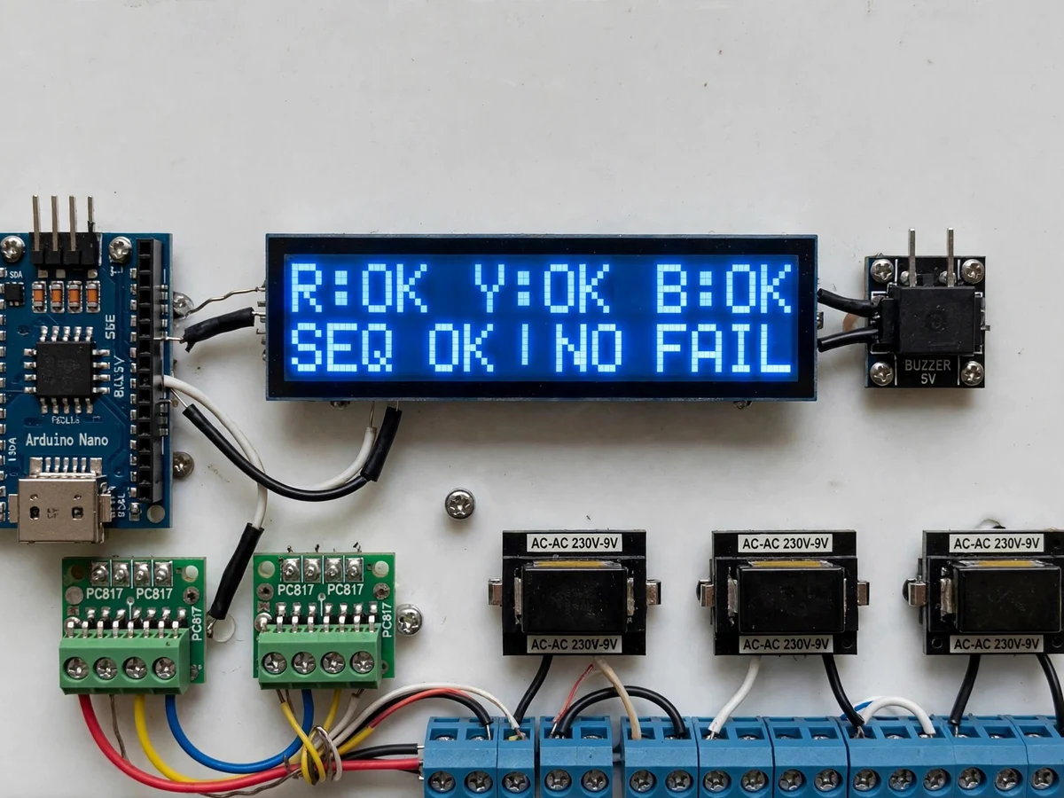
- [16x2 LCD status readout] The LCD continuously shows R/Y/B per-phase status on line one and the sequence verdict (SEQ OK / SEQ REV) plus any failure flag on line two, so the whole state is readable without a PC.
- [Buzzer fault alarm] A 5V active buzzer sounds on any declared fault — phase loss, reversed sequence or voltage fault — with a push-button to silence it, and it re-arms automatically on the next new fault.
- [R/Y/B indicator LEDs] Three panel LEDs mirror the per-phase status for at-a-glance checking from across the lab, each labelled with a handwritten masking-tape tag in the student-build style.
- [Transformer-isolated, optocoupler-buffered sensing] The three-phase input is stepped down by three separate transformers and each channel is optocoupler-buffered, so the ATmega328P side is galvanically isolated from the mains side by design.
- [Under/over-voltage fault flags] Each transformer secondary is also read through a divider into the 10-bit ADC; firmware compares the measured level against buyer-calibrated thresholds and flags phases that read too low or too high.
What is included
- Assembled indicator panel: controller board, sensing boards, LCD, buzzer, LEDs, transformers, terminal blocks and wiring
- Arduino Nano firmware (zero-crossing detection, sequence logic, threshold comparison, LCD + buzzer drivers)
- Circuit diagram and wiring diagram
- Voltage-threshold calibration procedure for the buyer's lab supply
- Project report PDF (background, sensing design, firmware logic, calibration, results)
- PPT presentation for final review
- Viva Q&A preparation document (zero-crossing detection, optocoupler isolation, phase sequence, fault timing)
Limitations & prerequisites
- The student demo is transformer-isolated and intended for a college lab three-phase supply; it is not a certified mains protection panel and must not be installed permanently on 400V distribution without a certified enclosure and earthing, which is not part of the student build.
- The 80–200 ms fault declaration time is a design target; the actual figure depends on the assembled build and wiring, and is verified with the buyer-run test procedure during delivery.
- Voltage-fault thresholds are approximate: transformer regulation is typically ±10% and the 10-bit ADC resolves about 5 mV per step after the divider, so the delivered calibration procedure sets thresholds against the buyer's own lab supply.
- Sequence detection assumes reasonably balanced phases; heavily unbalanced or harmonic-rich supplies can misread the phase order, which the report documents honestly.
- This is indication only: the build does not trip a contactor or disconnect a motor on fault — a trip output is future scope, not part of the delivered panel.
- The buzzer is an alert, not an alarm system: it can be muted with the push-button and it re-arms only on the next new fault, so unattended faults can go unnoticed once silenced.
- Demonstrating it needs a three-phase supply in the college lab; a single-phase household socket cannot exercise sequence or phase-failure detection.
Frequently Asked Questions
How does it detect wrong phase sequence?
Each phase's zero-crossing pulse is timestamped by the Arduino Nano. The firmware checks the arrival order: R-Y-B is reported as SEQ OK and R-B-Y as SEQ REV. A reversed sequence is what runs a three-phase motor backwards, so catching the order — not just the presence — is the point of the detection.
Does it connect directly to 400V mains?
No. The build is transformer-isolated by design: three 230V-to-9V transformers step the mains down, and each channel passes through a PC817 optocoupler, so the controller side never touches high voltage directly. It is meant to be demonstrated in a college lab on a proper three-phase supply.
What exactly does the LCD show?
Line one shows per-phase status (R:OK Y:OK B:OK, with any failed phase flagged), and line two shows the sequence verdict (SEQ OK or SEQ REV) plus any failure flag. The three R/Y/B panel LEDs mirror the per-phase status for at-a-glance checking.
Does it cut power to a motor when a fault occurs?
No — this build is indication only: LCD, LEDs and buzzer. It does not trip a contactor or disconnect anything. Adding a relay/contactor trip output is listed as future scope in the report, and is deliberately not claimed as implemented.
How fast does it declare a fault?
The design target is 80–200 ms after a phase disappears or a sequence reverses, based on counting missing zero-crossing half-cycles. This is stated as a design target, not a measured figure — the actual build is verified with the buyer-run test procedure during delivery.
Is this project suitable for a final-year project?
Yes — for Electrical, E&TC and IoT programs. It covers transformer isolation, optocoupler interfacing, zero-crossing detection, real-time firmware logic and panel assembly, all demonstrable and explainable in a viva. Suitable for B.E./B.Tech final-year projects in Electrical, E&TC and IoT.
Components & software requirements
- ATmega328P · Arduino Nano (firmware in Arduino C)
- PC817 optocouplers · zero-crossing detection
- 3 × 230V-to-9V AC transformers · galvanic isolation
- 16x2 character LCD (HD44780)
- 5V active piezo buzzer
- R/Y/B panel LEDs · terminal blocks
- White acrylic panel assembly
- Resistor dividers · 10-bit ADC voltage sensing
Delivery information
Built-to-order project. Delivery timeline is shared after order confirmation based on current queue.
Support terms
Complete documentation, setup guide, and viva preparation included. Support for setup and explanation provided.
Download free synopsis (PDF)
Enter your name and email — the synopsis PDF downloads immediately. We may send occasional project updates; no spam, unsubscribe anytime.