
More project photos (3)
The problem
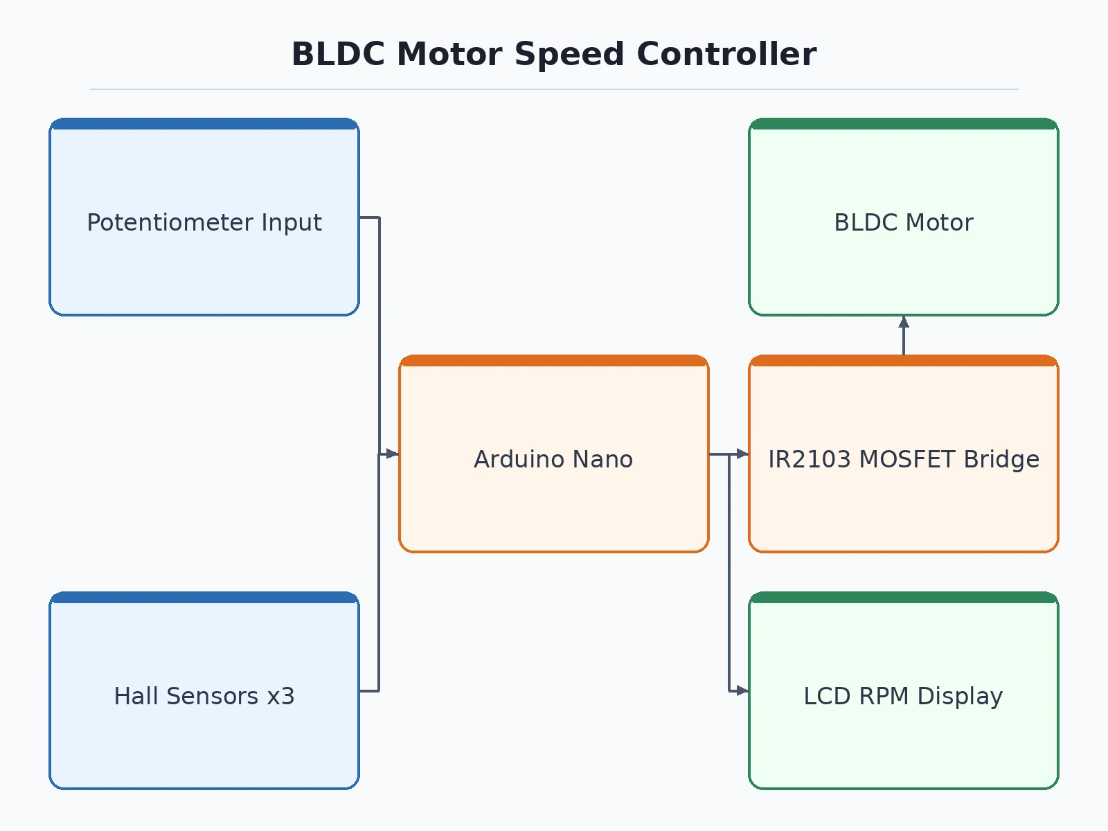
A brushless DC motor cannot run from a plain DC supply because its stator windings must be energised in the correct sequence as the rotor turns. Learners often buy a ready-made electronic speed controller that hides this sequencing entirely, so the core ideas of rotor-position sensing, commutation and gate driving are never understood. This project builds the controller openly instead: three Hall-effect sensors inside the motor report rotor position, an Arduino Nano decodes that state and switches three half-bridges in six-step trapezoidal commutation, and a potentiometer sets the PWM duty that controls speed. Direction switching, an LCD speed readout and a hardware overcurrent trip make the drive complete enough to study, measure and explain stage by stage.
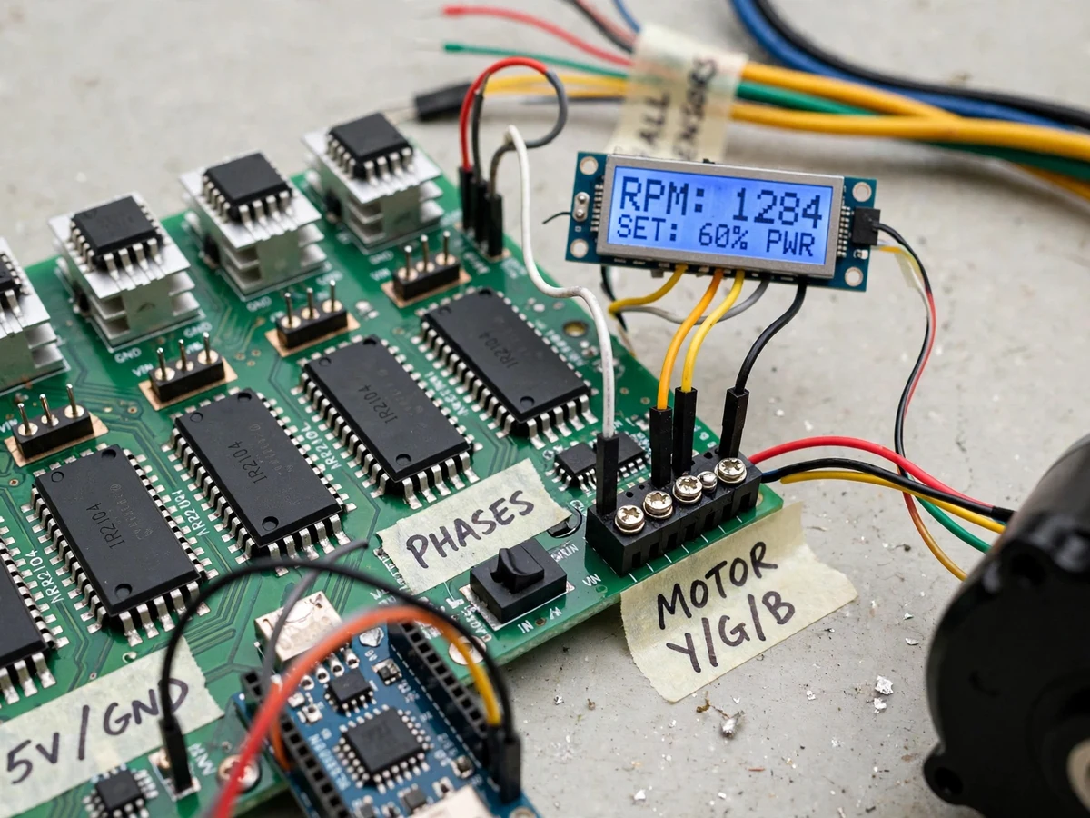
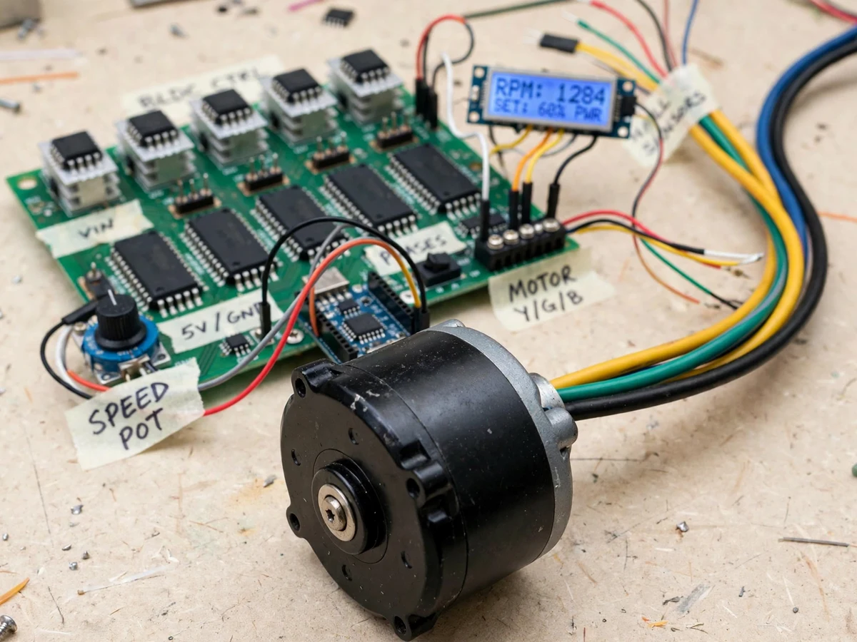
Three Hall sensors at 120 electrical degrees report rotor position as a three-bit code.
Follow the working sequence
How it works
- Three Hall-effect sensors in the motor produce a three-bit rotor-position code that changes every 60 electrical degrees as the rotor turns.
- The Arduino Nano (ATmega328P) reads the Hall code on digital inputs and looks up which two of the three motor phases to energise from the six-step commutation table.
- The potentiometer on an analog input sets the speed reference; the firmware converts it to a PWM duty value that chops the active phase drive.
- Commutation outputs drive three IR2103 half-bridge gate drivers, one per phase, which level-shift the logic signals to drive the high-side and low-side MOSFETs.
- Six IRF540N MOSFETs in the three half-bridges connect the selected phases to the DC bus and ground, producing the rotating stator field that pulls the rotor forward.
- Each Hall transition times the interval between pulses; the firmware converts pulse frequency to RPM and updates the 16x2 LCD readout.
- Bus current through the shunt resistor is watched by a comparator; an overcurrent event disables the gate drivers and lights a fault indicator until reset.
Tech stack:
- Arduino Nano (ATmega328P)
- Three Hall-effect sensors (in-motor)
- IR2103 half-bridge gate drivers
- IRF540N power MOSFETs
- Six-step trapezoidal commutation firmware
- PWM speed control (Arduino IDE, C/C++)
- 16x2 LCD display
- Comparator-based overcurrent trip
| Parameter | Value |
|---|---|
| Controller | Arduino Nano, ATmega328P, 16 MHz clock (datasheet) |
| Motor type | Sensored three-phase BLDC motor (design target) |
| DC bus voltage | Approximately 24 V DC (design target) |
| Commutation method | Six-step trapezoidal, Hall-sensored (design target) |
| Hall sensors | 3 units at 120-degree placement (design target) |
| Gate driver | IR2103 half-bridge, 600 V class, 10 V to 20 V supply range (datasheet) |
| Gate driver output | 0.21 A source, 0.36 A sink peak current (datasheet) |
| Power MOSFET | IRF540N, 100 V Vds rating, 33 A Id rating at 25 °C case temperature (datasheet) |
| PWM frequency | Approximately 16 kHz (design target) |
| Speed setting | Potentiometer, 0 % to 100 % duty range (design target) |
| RPM display | 16x2 LCD characters, Expected accuracy component-dependent |
| Protection | Shunt and comparator overcurrent trip, threshold set by resistor divider (design target) |
Project features
- [Sensored six-step commutation] Three Hall-effect sensors placed at 120 electrical degrees report rotor position, and the firmware energises the correct two phases for each of the six Hall states in trapezoidal sequence.
- [Three half-bridge power stage] Three IR2103 half-bridge gate drivers switch six IRF540N MOSFETs mounted on heatsinks, forming a three-phase bridge fed from the DC bus.
- [PWM speed control] A panel potentiometer sets the speed reference; the Nano varies the PWM duty applied during commutation, so motor speed follows the knob position smoothly from standstill upward.
- [Direction control] A toggle switch selects forward or reverse rotation by reversing the commutation sequence order in firmware, with the drive stopped before the sequence is flipped.
- [LCD RPM readout] Hall pulse timing is counted in firmware and converted to revolutions per minute, shown on a 16x2 LCD alongside the set duty percentage.
- [Overcurrent trip protection] A low-value shunt resistor in the DC bus feeds a comparator; when bus current crosses the set threshold, the comparator disables the gate drive until the fault is cleared.
- [Open firmware and wiring] The commutation table, PWM setup and RPM calculation are in commented Arduino code, and every power and signal wire is documented so the build can be traced and modified.
What is included
- Working BLDC speed-controller prototype with sensored BLDC motor
- Arduino Nano firmware source code with commented commutation table
- Circuit diagram and point-to-point wiring documentation
- Component list with part numbers (Nano, IR2103, IRF540N, Hall motor, LCD)
- Setup and calibration guide (Hall sequence check, trip threshold setting)
- Project report PDF (theory, commutation, gate drive, methodology, results)
- PPT presentation for final review
- Viva Q&A preparation document (BLDC theory, six-step commutation, PWM, gate driving)
Limitations & prerequisites
- The controller drives sensored motors only; sensorless back-EMF commutation is not implemented in the base build.
- Six-step trapezoidal drive produces more torque ripple and acoustic noise than sinusoidal or field-oriented control, especially at low speed.
- Starting under heavy mechanical load can stall the rotor; the drive expects light to moderate loads appropriate to a bench prototype.
- RPM readout accuracy depends on Hall pulse timing and motor pole count being set correctly in firmware; values are Expected, not calibrated measurements.
- The overcurrent trip is a basic shunt and comparator circuit, not a certified protection system, and its threshold is Approximate until set on the bench.
- The prototype runs from a bench DC supply at Approximately 24 V (design target); it is not an industrial-certified motor drive.
Frequently Asked Questions
Which controller and drive method are used?
An Arduino Nano based on the ATmega328P runs the drive. It reads the three Hall sensors, looks up the six-step trapezoidal commutation state, and outputs PWM-chopped drive signals to three IR2103 half-bridge drivers. This keeps the control logic readable in plain Arduino code that a student can step through, modify and explain without a dedicated motor-control processor.
Why does the motor need Hall sensors?
A brushless motor has no brushes or commutator, so the controller must know rotor position before it can energise the right phases. The three Hall sensors, spaced at 120 electrical degrees, give six valid position codes per electrical cycle. Each code maps to one commutation step, which is why sensored drive starts reliably from standstill, unlike basic sensorless drives.
What power supply does the project need?
The prototype is designed for a bench DC supply of Approximately 24 V (design target) for the motor bus, with regulated lower-voltage rails derived for the gate drivers and logic. Current capacity should suit the chosen motor, and the shunt-based overcurrent trip should be set before running the motor under load for the first time.
Can the speed and direction both be controlled?
Yes. A potentiometer sets the PWM duty and therefore the speed reference across the full duty range, and a toggle switch reverses the commutation sequence to change direction. Direction is changed at standstill in the base build; reversing a spinning motor under load is not supported and would stress the MOSFET bridge.
Is this project suitable for a final-year project?
Yes, for Electrical Engineering and related power-electronics programs. It demonstrates BLDC motor theory, Hall-effect position sensing, six-step commutation, MOSFET gate driving with IR2103 drivers, PWM speed control and protection design in one bench build. Every stage can be probed with a multimeter or oscilloscope, which gives concrete measurements and waveforms to present during review.
Components & software requirements
- Arduino Nano (ATmega328P)
- Three Hall-effect sensors (in-motor)
- IR2103 half-bridge gate drivers
- IRF540N power MOSFETs
- Six-step trapezoidal commutation firmware
- PWM speed control (Arduino IDE, C/C++)
- 16x2 LCD display
- Comparator-based overcurrent trip
Delivery information
Built-to-order project. Delivery timeline is shared after order confirmation based on current queue.
Support terms
Complete documentation, setup guide, and viva preparation included. Support for setup and explanation provided.
Download free synopsis (PDF)
Enter your name and email — the synopsis PDF downloads immediately. We may send occasional project updates; no spam, unsubscribe anytime.