
More project photos (3)
The problem
A Smart Traffic Light Controller with Density-Based Signal Timing using Arduino and IR Sensors is a tabletop 4-way intersection model that replaces fixed signal timers with green-light durations set by actual lane queues. Small IR obstacle-sensor modules mounted at each lane's stop line detect waiting vehicles, and an Arduino Uno converts those counts into proportional green time for every approach, so a crowded lane holds green longer while an empty lane gets the minimum or is skipped. When every sensor reads zero, the controller falls back to an equal fixed-time cycle so the intersection never stalls. The build demonstrates the complete embedded-control loop of sensing, counting, timing computation and signal actuation on a lane-queue model that is easy to show to an examiner. It does not manage real traffic: the sensors measure waiting queues at a model stop line, not live road flow, and every timing value is a configurable design parameter rather than a measured result.
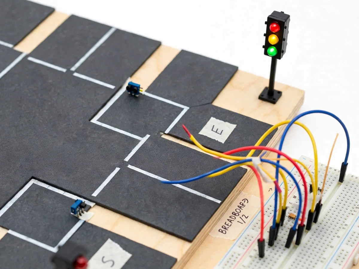
IR obstacle modules at each stop line report whether a vehicle is waiting.
Follow the working sequence
How it works
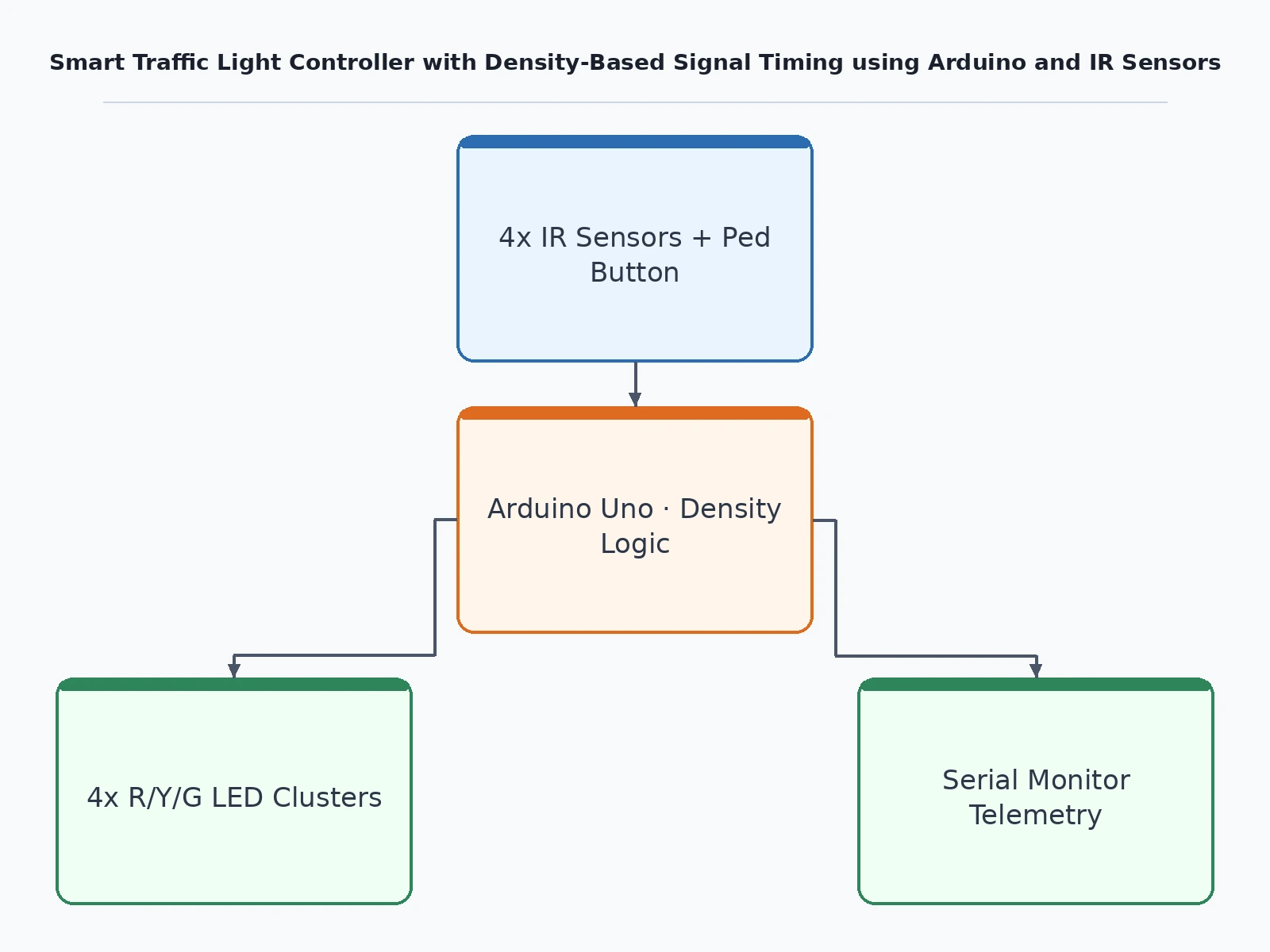
The mechanism runs in a closed loop of sensing, counting, timing computation and signal actuation. At each lane's stop line an IR emitter fires an invisible infrared beam across the lane; when a vehicle interrupts the beam, the receiver's output pin drops low and the Arduino registers one more waiting vehicle in that lane's queue. The firmware scans all four lanes at the start of every cycle, totals the queue counts, and divides the available green budget proportionally, so a lane holding half the waiting vehicles gets roughly half the green time, clamped between a 10 s minimum and a 60 s maximum (both configurable design parameters). The Arduino then switches the LED clusters: green for the active lane, a yellow clearance of about 3 s (design target), red for the rest, rotating through all four approaches. If every sensor reads zero, the controller abandons the density math and runs an equal fixed-time round-robin until traffic reappears.
- Mount one IR obstacle-sensor module at each lane's stop line, 4–6 cm above the road surface and angled 10–15° inward across the lane — straight-on mounting false-triggers on adjacent-lane traffic.
- Place model vehicles at the stop lines; each vehicle interrupting a sensor beam pulls that sensor's output low, and the firmware counts the lane as occupied.
- At the start of each cycle the Arduino scans the four sensor outputs, builds a per-lane queue count and sums them into the cycle total.
- Green time per lane is computed as (lane count ÷ total count) × green budget, clamped to the configurable 10–60 s window; empty lanes get the minimum or are skipped per the skip-empty-lane setting.
- The Arduino drives the signal clusters in phase order — green on the active lane, yellow for the ~3 s (design target) clearance interval, red on the others — rotating through all four approaches.
- If all four sensors read zero, the firmware switches to the fixed-time fallback: equal green per lane in round-robin until a sensor detects a vehicle again.
Tech stack:
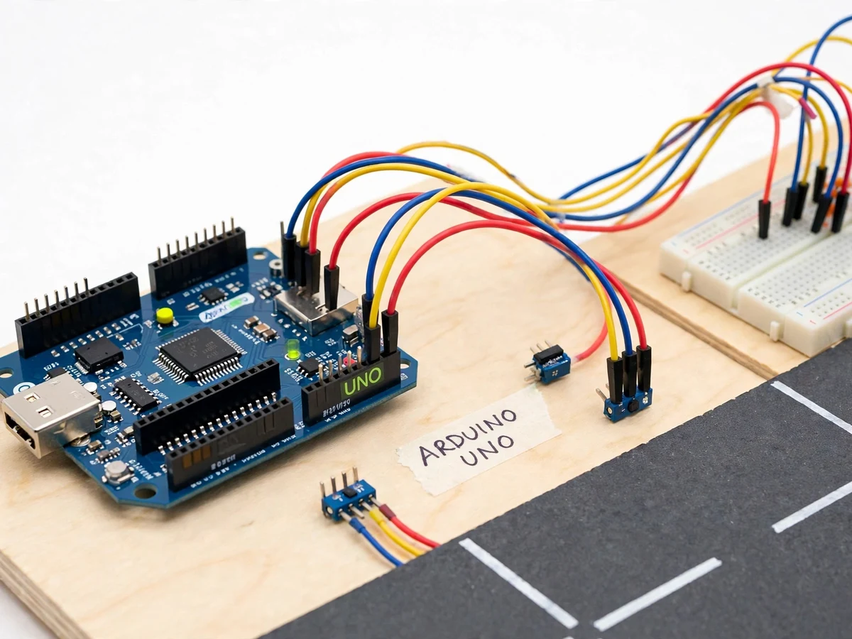
- Arduino Uno (ATmega328P)
- IR obstacle-sensor modules (4)
- Red · yellow · green LED signal clusters
- NPN transistor LED driver stages
- Breadboard + jumper wiring
- Optional pedestrian push-button
- Arduino IDE (C/C++ firmware)
- Serial monitor (queue telemetry)
| Parameter | Value |
|---|---|
| Controller | Arduino Uno (ATmega328P), 16 MHz clock (datasheet) |
| Vehicle sensing | IR obstacle-sensor modules; detection range 2–30 cm (datasheet) |
| Intersection model | 4-way tabletop model; lane width approximately 6–8 cm (prototype-dependent) |
| Signal clusters | 4 × red/yellow/green LED clusters, transistor-driven |
| Green-time window | 10–60 s per phase (design parameter, configurable) |
| Yellow clearance | Approximately 3 s (design target, configurable) |
| Queue resolution | One presence reading per lane per cycle (Approximate, prototype-dependent) |
| Fallback behavior | Equal fixed-time round-robin when all lanes read zero (design) |
| Pedestrian input | Optional push-button; firmware option, unwired in base build |
| Power | 5 V DC regulated for logic and sensors; USB or adapter |
| Telemetry | Serial monitor at 9600 baud (design) |
Project features
The heart of the build is density-proportional green timing: instead of every lane getting the same fixed green, the Arduino divides each cycle's green budget according to the queue counts from the four IR sensor modules, so a lane with six waiting vehicles holds green roughly three times longer than a lane with two. Per-lane IR queue sensing does the counting, with each stop-line sensor reporting one binary presence reading that the firmware turns into a per-lane queue figure. A fixed-time fallback takes over whenever all lanes read empty, running an equal round-robin cycle so the demo never freezes. Finally, four LED signal clusters with red, yellow and green give each approach a real, examinable signal head driven through transistor stages. Together these four capabilities make the project a complete sensing-to-actuation loop rather than a decorative light chaser.
- [Density-proportional green timing] Each cycle, the Arduino converts the four lane-queue counts into green durations clamped inside a configurable 10–60 s window; a lane with no detected vehicles gets the minimum green or is skipped, per the skip-empty-lane setting.
- [Per-lane IR queue sensing] IR obstacle-sensor modules at each stop line detect waiting vehicles within their 2–30 cm (datasheet) range; the firmware scans all four lanes and builds a per-lane queue count every cycle.
- [Fixed-time fallback cycle] If every sensor reads zero, the firmware runs an equal-duration round-robin cycle so the intersection keeps cycling safely instead of stalling on an empty lane.
- [Four-way LED signal clusters] Each approach gets a red/yellow/green LED cluster driven by the Arduino through transistor driver stages, with a configurable yellow clearance interval between phase changes.
- [Live queue telemetry over serial] The firmware prints per-lane counts and the computed green times to the serial monitor, so the density-to-timing computation is visible and verifiable during the demonstration.
- [Configurable timing constants] The green window, yellow clearance, skip-empty-lane behavior and fallback cycle time are firmware constants the buyer tunes for their own model; nothing is hard-coded.
- [Pedestrian crossing button (optional)] An optional push-button input inserts a pedestrian crossing phase; it ships as a firmware option and is unwired in the base build.
What is included
- Tabletop 4-way intersection model base with lane markings
- Arduino Uno board + USB cable
- 4 IR obstacle-sensor modules with mounting hardware
- 4 red/yellow/green LED signal clusters with transistor driver stage
- Half-size breadboard and jumper wire set
- Optional pedestrian push-button (ships loose, wiring guide included)
- Complete firmware source code (sensing, timing computation, fallback, telemetry)
- Circuit and wiring documentation with sensor-mounting builder notes
- Sensor placement and threshold-tuning procedure (buyer-run)
- Project report PDF (background, sensing-to-timing theory, methodology, demo procedure)
- PPT presentation for final review
- Viva Q&A preparation document (IR sensing, timing algorithms, embedded control)
Limitations & prerequisites
- This is a lane-queue tabletop model, not a real intersection deployment — it must never be connected to or presented as real traffic infrastructure.
- The sensors measure waiting vehicles at the model's stop lines; they do not measure live traffic flow, speed or vehicle type.
- IR detection range is 2–30 cm (datasheet); direct sunlight and reflective surfaces can false-trigger readings, and the mounting geometry (4–6 cm height, 10–15° inward angle) must be tuned on the buyer's own build.
- Queue resolution is one presence reading per lane per cycle — closely spaced vehicles can read as one, so timing is proportional to detected presence, not an exact vehicle count.
- All timing values (10–60 s green window, ~3 s yellow) are configurable design parameters, not measured or certified traffic-engineering timings.
- The prototype ships uncalibrated; final sensor thresholds and timing constants are set by the buyer using the included procedure.
Frequently Asked Questions
How does the density-based timing actually work?
Each IR sensor at a lane's stop line reports whether a vehicle is waiting; the Arduino totals the four lanes' counts and gives each lane green time in proportion to its share of the queue, clamped inside a configurable 10–60 s window. A lane with no waiting vehicles gets the minimum green or is skipped, and when every lane is empty the controller falls back to an equal fixed-time cycle. The computed green times print to the serial monitor, so the allocation is visible live during the demo, and every constant can be retuned for the buyer's model.
What is the real detection range of the IR sensors?
The common IR obstacle-sensor modules used here are rated 2–30 cm on their datasheet, which suits a tabletop lane. The builder guide mounts each module 4–6 cm above the road surface, angled 10–15° inward across the lane — straight-on mounting false-triggers on adjacent-lane traffic. The on-module potentiometer sets the trigger threshold, and the tuning procedure walks the buyer through adjusting it on their own build, away from direct sunlight that can swamp the receiver.
What happens when there is no traffic at the model?
The firmware detects the all-zero reading and switches to a fixed-time fallback: equal green for each lane in round-robin until a sensor sees a vehicle again. The intersection never stalls on an empty lane and never holds green indefinitely while other approaches wait for their turn. This fallback is the safety net that makes the demo robust — an examiner can watch it cycle with no vehicles placed, then drop vehicles in and watch the timing stretch and shrink with the queue.
Can this controller manage a real road intersection?
No — this is a lane-queue demonstration model, not equipment for a real road: the sensors only see waiting model vehicles at a stop line, never real traffic, and every timing value is a student-set design parameter rather than an approved traffic-engineering signal plan. Real signals require certified controllers, failsafe lamp interlocking and authority-approved timing plans that this build does not replicate. What the project does teach is the genuine control loop behind the idea — presence sensing, queue counting, proportional allocation and multi-channel actuation — which is exactly what examiners ask about.
Is the pedestrian crossing button included?
Yes, as an optional firmware feature with a push-button shipped loose in the kit. When enabled, pressing it inserts a pedestrian crossing phase into the cycle; in the base build it is unwired so the core four-phase density demo stays simple. The wiring guide shows where it connects and which firmware flag turns it on, so adding it is a five-minute job if the student wants the extra talking point.
Is this project suitable for a final-year project?
Yes — for Electronics, Embedded Systems and IoT programs. It combines IR sensing, real-time counting, a proportional timing algorithm and multi-channel actuation in one demonstrable build, with strong viva material in sensor physics, embedded control logic and the reasoning behind every timing constant. The working model gives the examiner something to watch change as vehicles are added or removed, which is exactly what makes a hardware demo convincing.
Components & software requirements
- Arduino Uno (ATmega328P)
- IR obstacle-sensor modules (4)
- Red · yellow · green LED signal clusters
- NPN transistor LED driver stages
- Breadboard + jumper wiring
- Optional pedestrian push-button
- Arduino IDE (C/C++ firmware)
- Serial monitor (queue telemetry)
Delivery information
Built-to-order project. Delivery timeline is shared after order confirmation based on current queue.
Support terms
Complete documentation, setup guide, and viva preparation included. Support for setup and explanation provided.
Download free synopsis (PDF)
Enter your name and WhatsApp number — the synopsis PDF downloads immediately. We may send occasional project updates on WhatsApp; no spam.