
More project photos (2)
The problem
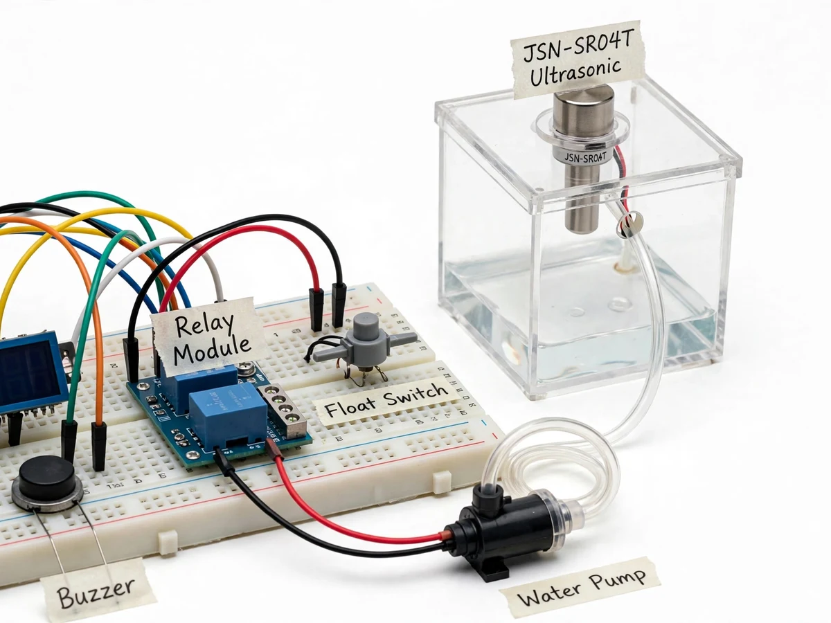
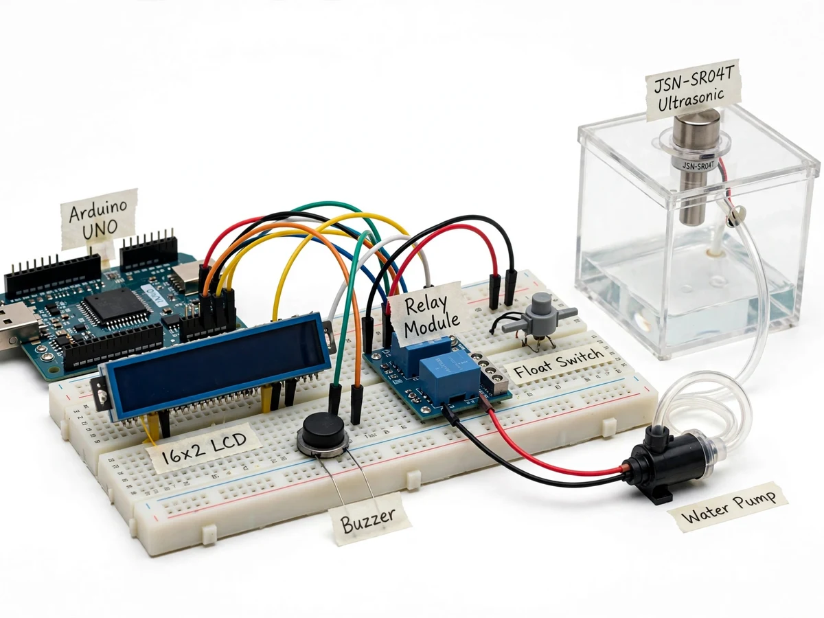
Every Indian household knows the routine: switch the pump on, forget it, and watch water pour off the terrace — or worse, run the pump dry when the sump is empty and burn the motor. This controller removes the human from the loop. A waterproof JSN-SR04T ultrasonic sensor mounted under the tank lid measures the water level continuously; the controller switches the pump through a contactor/relay at the low-level mark and cuts it at the full mark, with hysteresis so the pump doesn't chatter at the boundary. A second sensor (or float switch) on the sump/ground tank interlocks the pump: no water below, no pumping, and the buzzer plus LCD announce the dry condition. A manual mode covers testing, and a pump-runtime log helps spot abnormal cycles. The scope is stated plainly: it automates a domestic single-pump setup — it is not a municipal waterworks controller.
How it works
- The JSN-SR04T pings the water surface at fixed intervals; the echo time converts to distance, then to level percent against the buyer-calibrated empty/full marks.
- When the level falls to the low mark, the controller energizes the pump relay/contactor and logs a start event.
- When the level reaches the full mark, the controller drops the pump and logs a stop event; the hysteresis band keeps the pump from short-cycling.
- Before every start — and continuously while running — the sump interlock is checked; a dry sump blocks or stops the pump and raises the buzzer + LCD fault.
- The LCD shows live level, pump state and any fault; the manual switch bypasses automation for testing, flagged clearly on screen.
- The event log (level crossings, pump cycles, dry-run blocks) is kept for the report's data section and the buyer's own verification.
Tech stack:
- Arduino Uno (ATmega328P) or ESP32 variant
- JSN-SR04T waterproof ultrasonic sensor
- Sump float switch / second level sensor (interlock)
- Pump relay/contactor module
- 16x2 character LCD + buzzer
- Manual override switch
- Arduino IDE (C/C++ firmware)
| Parameter | Value |
|---|---|
| Controller | Arduino Uno (or ESP32), level state machine with hysteresis |
| Level sensing | JSN-SR04T waterproof ultrasonic, non-contact; empty/full marks buyer-calibrated |
| Pump control | Relay/contactor output; start at low mark, stop at full mark, configurable dead band |
| Dry-run protection | Sump interlock blocks/ends pumping; buzzer + LCD fault annunciation |
| Display | 16x2 LCD: level %, pump state, fault flags |
| Logging | Pump start/stop + level-crossing event log |
| Power | 5 V DC logic; pump switched through relay/contactor (demo pump) |
Project features
- [Non-contact level sensing] Waterproof JSN-SR04T ultrasonic sensor measures tank level from under the lid — no floats to jam, no probes to corrode.
- [Automatic pump control] Pump starts at the buyer-set low level and stops at the full level, with hysteresis preventing rapid on/off cycling.
- [Dry-run protection] Sump-low interlock blocks pumping when the source is empty, protecting the motor; LCD + buzzer announce the condition.
- [Hysteresis band control] Separate start and stop levels with a configurable dead band — proper control practice, documented in the report.
- [LCD level display] Live level in percent plus pump ON/OFF state and fault flags on a 16x2 LCD.
- [Manual override mode] Panel switch forces manual pump control for testing and priming, with the LCD flagging MANUAL mode.
- [Pump runtime log] Start/stop events with timestamps are logged, so abnormal cycling shows up in the data for the report.
What is included
- Working overflow-controller prototype (controller, JSN-SR04T, sump interlock, pump relay, LCD, buzzer, demo tanks/pump)
- Complete firmware source code (level measurement, hysteresis control, dry-run interlock, logging)
- Circuit and wiring documentation with relay/contactor safety notes
- Component list with ratings
- Level-calibration and demo procedure guide
- Project report PDF (level-sensing background, ultrasonic theory, hysteresis control, methodology, test procedure)
- PPT presentation for final review
- Viva Q&A preparation document (ultrasonic ranging, hysteresis, contactor driving, dry-run physics)
- Setup and demonstration guide
Limitations & prerequisites
- Demonstrated on scaled demo tanks with a small demo pump; real terrace-tank wiring and plumbing are the buyer's deployment by a qualified electrician/plumber.
- Ultrasonic readings need the buyer's own empty/full calibration; foam, steam or sloped tank lids can disturb readings — documented in the setup guide.
- The sump interlock needs its own sensor/float fitted at the source; the base prototype demonstrates it on the demo rig.
- Pump ratings are limited to the relay/contactor fitted; switching a large borewell pump needs a contactor sized by the buyer.
- Event timestamps need an RTC module (listed as an option); the base build logs sequence without wall-clock time.
Frequently Asked Questions
How does it detect the water level?
A waterproof JSN-SR04T ultrasonic sensor under the tank lid measures the distance to the water surface — non-contact, so nothing jams or corrodes. Empty/full marks are calibrated during setup.
How does it prevent dry running?
A sump-low interlock (float switch or second sensor) blocks the pump from starting — and stops it — when the source is empty, with buzzer and LCD annunciation.
Will the pump switch on and off repeatedly near the level marks?
No — separate start and stop levels with a configurable hysteresis dead band prevent short-cycling; this is documented control practice.
Can it control my home's actual pump?
The prototype demonstrates the logic on demo tanks. Connecting to real household wiring must be done by a qualified electrician with a properly rated contactor.
What are the main limitations?
Scaled demo rig, buyer calibration needed, ultrasonic limits (foam/steam), pump sizing by buyer.
Is this project suitable for a final-year project?
Yes — for IoT and Embedded Systems programs. It covers ultrasonic sensing, hysteresis control, interlock safety logic and relay driving, all strong viva material. Suitable for B.E./B.Tech final-year projects in IoT and Embedded Systems.
Components & software requirements
- Arduino Uno (ATmega328P) or ESP32 variant
- JSN-SR04T waterproof ultrasonic sensor
- Sump float switch / second level sensor (interlock)
- Pump relay/contactor module
- 16x2 character LCD + buzzer
- Manual override switch
- Arduino IDE (C/C++ firmware)
Delivery information
Built-to-order project. Delivery timeline is shared after order confirmation based on current queue.
Support terms
Complete documentation, setup guide, and viva preparation included. Support for setup and explanation provided.