
More project photos (3)
The problem
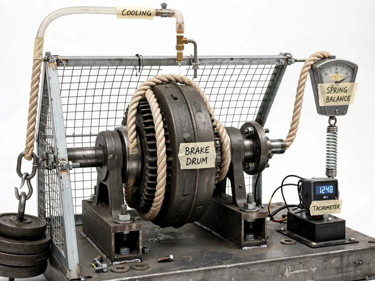
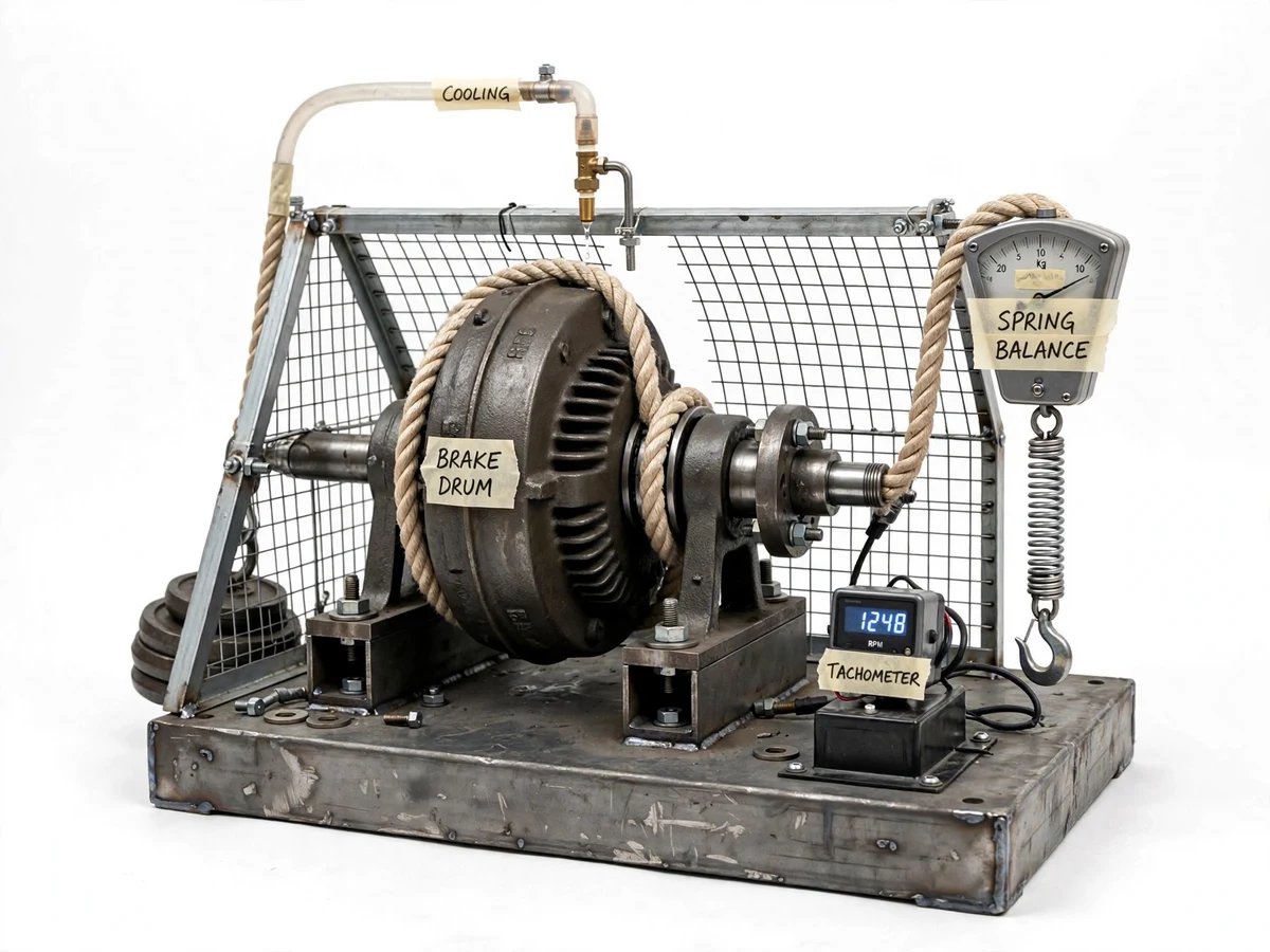
Brake power — the usable power an engine delivers at its shaft — is the single most quoted engine performance figure, yet most students only ever compute it from textbook numbers. A dynamometer is the instrument that makes it real: it absorbs the shaft power as friction and measures the resisting torque. The rope brake dynamometer is the simplest absorption type: a rope passes over a brake drum keyed to the engine shaft, dead weights hang on the tight side and a spring balance reads the slack side, and the torque follows from the tension difference times the drum radius. Combined with a speed reading, brake power is BP = 2πNT/60,000 kW. This project builds that rig at lab scale — brake drum, rope, loading weights, spring balances, drip cooling and a safety guard on a rigid bedplate with a flexible coupling to the test engine — so the student loads the engine in steps, records tensions and speed, and plots the brake-power curve from their own measurements.
Engine under test, coupled to the brake drum on the bedplate.
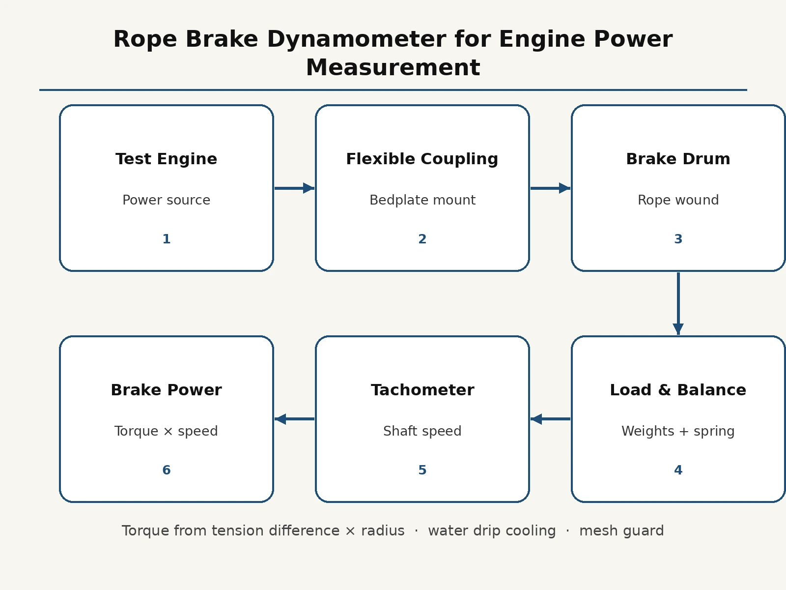
Follow the working sequence
How it works
- The brake drum is keyed to the test engine shaft (or a drive motor standing in for the engine) through the flexible coupling on the bedplate.
- The rope is wound over the drum with dead weights hung on the tight side and the spring balance attached on the slack side.
- The engine is started and brought to the test speed; cooling water drip is opened over the drum.
- At each load step the student records the spring-balance reading (slack-side tension) and the shaft speed from the tachometer.
- Braking torque is computed as (tight-side tension − slack-side tension) × effective drum radius, using the calculation sheets.
- Brake power follows from torque and speed; repeating at several loads and speeds builds the engine's brake-power curve for the report.
Tech stack:
- Machined CI brake drum on steel shaft
- Cotton brake rope with dead weights
- Spring balances (tension measurement)
- Digital tachometer
- Drip water-cooling arrangement
- Flexible jaw coupling
- Fabricated MS bedplate
- Wire-mesh safety guard
| Parameter | Value |
|---|---|
| Brake drum diameter | Approximately 300 mm (design target) |
| Rope | Cotton brake rope, approximately 20 mm dia (design target) |
| Test power range | Up to approximately 5 kW engines (design target) |
| Speed range | Approximately 500–1500 rpm (design target) |
| Torque measurement | From spring-balance and dead-weight readings (student-measured) |
| Cooling | Water drip on drum, approximately 2–4 L per run (expected) |
| Overall size | Approximately 1200 × 500 × 700 mm (design target) |
Project features
- [Rope-and-drum brake] A machined brake drum with a cotton rope wound over it — the classic absorption arrangement, simple to understand and maintain.
- [Dead-weight loading] Calibrated dead weights on the tight side with a spring balance on the slack side, so braking torque comes from direct force readings.
- [Water drip cooling] A drip-cooling arrangement on the drum carries away friction heat, allowing sustained loaded runs without rope damage.
- [Speed measurement] A digital tachometer on the drum shaft gives the speed reading needed alongside torque for the brake-power calculation.
- [Torque-to-power calculation sheets] Ready sheets walk the student from tension readings to torque to brake power at each load step, ending in a plotted performance curve.
- [Mesh safety guard] A wire-mesh guard encloses the rotating drum and rope, with the coupling covered, for safe student operation.
- [Rigid bedplate with coupling] A heavy fabricated bedplate with a flexible jaw coupling aligns the rig to small test engines (up to the design power range).
What is included
- Fully fabricated rope brake dynamometer rig with guard
- Dead weights, spring balances and digital tachometer
- Torque-to-brake-power calculation sheets and graph formats
- Cooling-water and loading procedure card
- Project report PDF (dynamometer theory, methodology, results format)
- PPT presentation for final review
- Viva Q&A preparation document (brake power, torque, absorption vs transmission dynamometers)
Limitations & prerequisites
- Brake power values are computed from the student's own readings — no performance figures are claimed as measured before the build.
- Friction heat limits continuous loaded running; the procedure specifies run/rest intervals and cooling flow.
- The rope wears with use and needs periodic replacement; a spare rope and the replacement procedure are included.
- Suited to small single-cylinder test engines or a drive motor as the prime mover — not for high-speed or high-power engines.
- Manual load stepping: load cannot be changed remotely or held automatically constant (a hydraulic dynamometer is future scope).
- Spring balances need zero-checking before each session, covered in the calibration card.
Frequently Asked Questions
How does a rope brake dynamometer measure power?
It doesn't measure power directly — it measures braking torque from the rope tension difference times drum radius, and speed from the tachometer. Brake power is then computed as 2πNT/60,000 kW. The rig teaches exactly this measurement chain.
Why is cooling needed?
All the absorbed shaft power turns into friction heat at the rope-drum interface. Without the water drip, the rope would overheat and fail during a loaded run — the cooling arrangement is a functional part of the design.
What engine can it be coupled to?
Small single-cylinder petrol or diesel test engines up to the design power range, through the flexible jaw coupling. A drive motor can stand in as the prime mover where an engine is unavailable.
Absorption vs transmission dynamometer — what's the difference?
An absorption dynamometer (like this rope brake) dissipates the power as heat; a transmission dynamometer passes the power through while measuring torque. The viva Q&A covers both with examples.
Is this project suitable for a final-year project?
Yes — for Mechanical and Automobile programs. It turns the brake-power formula into a real measurement exercise with loading, cooling and data plotting. Suitable for B.E./B.Tech final-year projects in Mechanical and Automobile Engineering.
Components & software requirements
- Machined CI brake drum on steel shaft
- Cotton brake rope with dead weights
- Spring balances (tension measurement)
- Digital tachometer
- Drip water-cooling arrangement
- Flexible jaw coupling
- Fabricated MS bedplate
- Wire-mesh safety guard
Delivery information
Built-to-order project. Delivery timeline is shared after order confirmation based on current queue.
Support terms
Complete documentation, setup guide, and viva preparation included. Support for setup and explanation provided.
Download free synopsis (PDF)
Enter your name and WhatsApp number — the synopsis PDF downloads immediately. We may send occasional project updates on WhatsApp; no spam.