
More project photos (2)
The problem
Compressed air drives thousands of factory tools, yet most mechanical students never measure what an air motor actually delivers at the shaft: how torque falls as speed rises, where peak power sits, and how much of the air's energy becomes useful work. Dynamometry chapters describe the rope brake on paper; a test rig makes it physical. This project builds a complete compressed-air engine test bench around a real rotary vane pneumatic motor of about 0.5 HP. A filter-regulator-lubricator unit sets clean, metered inlet air between 2 and 5 bar, and a rope-brake dynamometer — rope, brake drum, spring balance and dead weights — loads the output shaft while a tachometer reads speed. From those instruments come the classic performance curves: torque–speed, power–speed and power-versus-pressure. Every number in the student's report is measured on the student's own rig, which makes the viva discussion genuinely theirs.
The workshop compressor or lab air line supplies compressed air to the rig.
Follow the working sequence
How it works
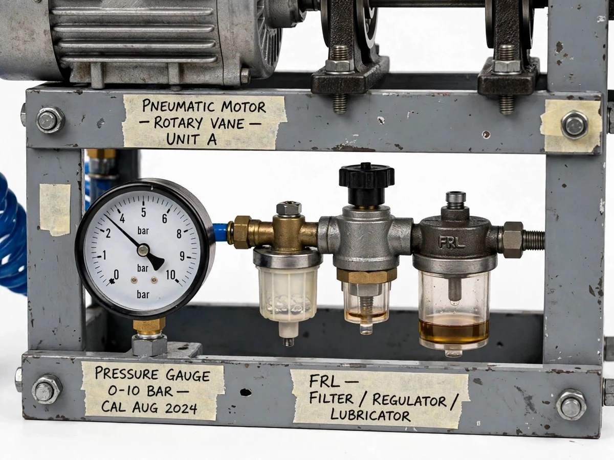
- A workshop compressor (2 HP class, 8 bar) or the college lab air line charges the rig through the FRL unit: the filter traps moisture, the regulator sets the test pressure on the 0–10 bar gauge, and the lubricator meters oil mist into the air stream.
- Pressurized air enters the vane motor's inlet port. The rotor sits off-centre in its bore, so centrifugal force flings each sliding vane outward until its tip seals against the housing wall; air trapped between two successive vanes pushes on the exposed vane face, and that pressure difference across the eccentric gap is what turns the shaft — no crankshaft, no valves.
- The rotor spins up with the rope brake slack; the tachometer records near-free speed at the set pressure — the no-load point of the curve.
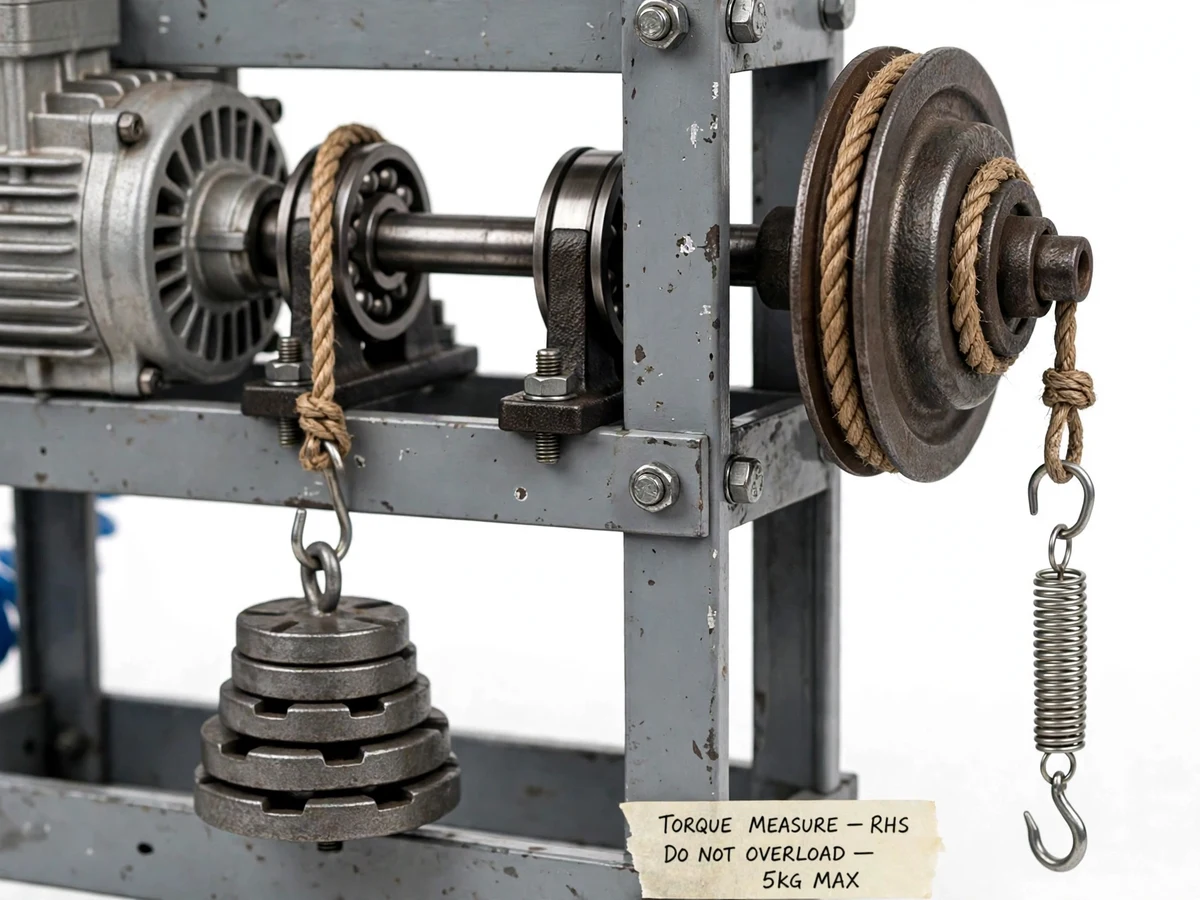
- Load is applied in steps: slotted weights go on the hanger (5 kg maximum, per the rig label), the rope tightens on the brake drum, and the spring balance reading is noted once the speed settles.
- At each step the student records inlet pressure, dead weight W, spring reading S and speed N, then computes braking torque T = (W − S)(D + d)/2 and brake power BP = (W − S) × π(D + d)N/60.
- The full matrix — pressures from 2 to 5 bar, loads from free-running to near-stall — is repeated, and the readings are plotted as torque–speed, power–speed and power-versus-pressure curves that reveal the motor's peak-power point.
- Builder note from the build: a vane motor is thirsty for oil — the FRL lubricator is set to show a faint mist at its sight dome, and the inlet gets a few drops of pneumatic-tool oil before the first run of the day. A dry vane motor is the single most common reason a freshly assembled rig refuses to turn.
Tech stack:
- Rotary vane pneumatic motor (~0.5 HP class)
- FRL unit (filter · regulator · lubricator)
- Rope-brake dynamometer (spring balance + weights)
- Non-contact digital tachometer
- MS angle frame · pillow-block bearings
- 0–10 bar pressure gauges
- Flexible jaw coupling
- Workshop air compressor (8 bar)
| Parameter | Value |
|---|---|
| Prime mover | Rotary vane air motor, ~0.5 HP class (datasheet: 0.45 HP, 10,000 rpm max, 7 bar max line, 0.65 N·m max torque — Gast 1AM class) |
| Test pressure band | 2–5 bar inlet (regulator 0–8 bar; rig label caps at 5 bar max) |
| Brake drum | Cast iron, 150 mm diameter (Approximate) |
| Torque measurement | Rope brake: T = (W − S)(D + d)/2 |
| Torque range | 0–0.5 N·m (Expected at ≤5 bar) |
| No-load speed | Up to approximately 8,000 rpm at 5 bar (Expected) |
| Brake power | Peak approximately 0.25–0.30 kW near 5 bar (Expected, design target) |
| Air consumption | Up to approximately 35 m³/h at full load (Datasheet value) |
| Speed instrument | Non-contact tachometer, 0–9,999 rpm instrument range |
| Weight hanger limit | 5 kg maximum (per rig label) |
| Frame | MS angle-iron, bolted, with exhaust muffler |
Project features
- [Real rotary vane air motor] A ~0.5 HP-class rotary vane pneumatic motor is the prime mover — datasheet of the referenced class: 0.45 HP, 10,000 rpm maximum, 7 bar maximum line pressure, 0.65 N·m maximum torque. No simulated engine, no electric stand-in.
- [FRL air preparation] The filter-regulator-lubricator unit strips moisture, sets inlet pressure on a 0–10 bar gauge and meters oil mist to the vanes, so every test runs on clean, lubricated air.
- [Rope-brake dynamometer] A hemp rope over a cast-iron brake drum, one end on a spring balance and the other on a dead-weight hanger, gives shaft torque from T = (W − S)(D + d)/2 — the textbook absorption dynamometer, built for real.
- [Tachometer speed pickup] A non-contact digital tachometer reads shaft speed from a reflective strip on the drum, so torque and speed are recorded together at every load step.
- [Rigid bolted frame] A painted MS angle-iron frame carries the motor, two pillow-block bearings and the drum shaft in one aligned line, with an exhaust muffler keeping lab noise down.
- [Performance-curve test procedure] The manual walks through the full test matrix — pressures from 2 to 5 bar, load steps up to near-stall — with blank observation tables and a worked brake-power calculation example.
What is included
- Working compressed-air engine test rig (motor, FRL unit, frame, rope brake, gauges, tachometer)
- Assembly and shaft-alignment documentation with fabrication drawings
- Test manual with blank observation tables and a worked brake-power calculation
- Build log including the lubrication note from the actual build
- Project report PDF (vane-motor theory, dynamometry, methodology, results section)
- PPT presentation for final review
- Viva Q&A preparation document (fluid power, torque measurement, performance curves)
Limitations & prerequisites
- Rope friction heats the drum and rope at sustained speed — tests run in short load steps, not continuous full-load duty.
- This is a pneumatic motor, not a combustion engine: there is no fuel, ignition or thermodynamic cycle analysis beyond air-expansion work.
- All torque and power figures are design targets from the motor datasheet; the student's own test readings fill the results section.
- Exhaust air is noisy without the muffler — hearing protection is recommended near the rig at full speed.
- Shop air must pass through the FRL: unfiltered moisture corrodes the bore and dry air scores the vanes.
- The rig is a lab demonstration test cell, not an industrial-certified dynamometer.
Build timeline
- Typical built-to-order timeline is approximately 3–4 weeks: frame fabrication and mechanical assembly in weeks 1–2, instrumentation fitting and calibration runs in week 3, report/PPT/viva kit in week 4. Timelines vary with component sourcing.
Support
- Assembly and alignment guidance over call/WhatsApp during setup, support through the first calibration runs, and report formatting adjusted to the student's college template.
Frequently Asked Questions
Is this project suitable for a final-year project?
Yes — for Mechanical and Automobile Engineering. It demonstrates fluid power, rotary vane motor working, absorption dynamometry and performance-curve testing, all classic lab-course topics in hardware form.
Does this "engine" burn any fuel?
No. The prime mover is a pneumatic vane motor that runs on compressed air — there is no combustion, fuel system or exhaust gas. The project is about measuring shaft power from expanding air, not about IC engines.
How is torque actually measured?
With a rope-brake dynamometer: a rope over the brake drum, dead weight W on one end and a spring balance reading S on the other. Torque is T = (W − S)(D + d)/2 and brake power is (W − S) × π(D + d)N/60, with N from the tachometer. The manual includes a worked example.
What air supply does the rig need?
A standard workshop compressor (2 HP class, 8 bar) or a college lab compressed-air line. The rig's own label caps test pressure at 5 bar and the hanger at 5 kg — the manual enforces both.
Which motor is used, and can it be changed?
The base build uses a ~0.5 HP-class rotary vane air motor (the datasheet referenced is the Gast 1AM class: 0.45 HP, 10,000 rpm maximum, 7 bar maximum). A larger 1.7 HP-class motor is an optional upgrade with a bigger drum and weights.
What are the main limitations?
Rope heating limits continuous running to short test steps, results depend on the actual compressor and motor used, and the rig is a teaching test cell — not a certified dynamometer. Full details are in the Limitations section.
Components & software requirements
- Rotary vane pneumatic motor (~0.5 HP class)
- FRL unit (filter · regulator · lubricator)
- Rope-brake dynamometer (spring balance + weights)
- Non-contact digital tachometer
- MS angle frame · pillow-block bearings
- 0–10 bar pressure gauges
- Flexible jaw coupling
- Workshop air compressor (8 bar)
Delivery information
Built-to-order project. Delivery timeline is shared after order confirmation based on current queue.
Support terms
Complete documentation, setup guide, and viva preparation included. Support for setup and explanation provided.
Download free synopsis (PDF)
Enter your name and WhatsApp number — the synopsis PDF downloads immediately. We may send occasional project updates on WhatsApp; no spam.