
More project photos (2)
The problem
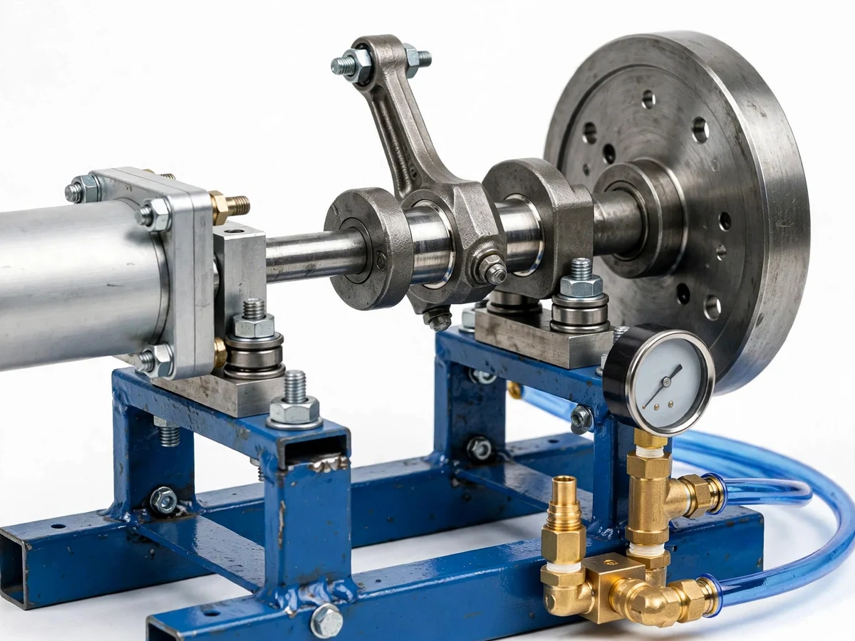
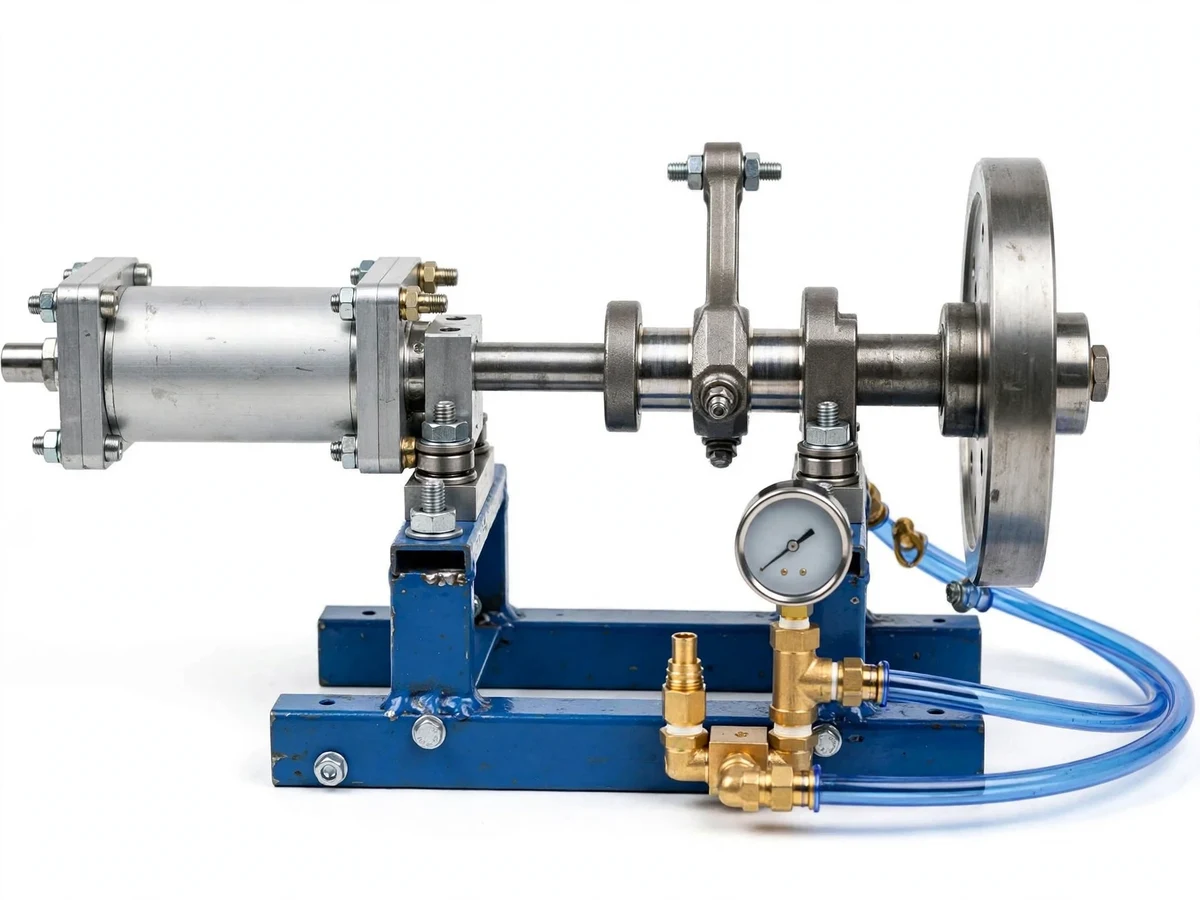
Before electric motors took over, compressed air drove real machinery — and the slider-crank engine that converts a piston's push into rotation is the same mechanism at the heart of every internal-combustion engine. This project rebuilds that idea as a clean student prototype: instead of fuel and spark, a double-acting pneumatic cylinder fed by shop air drives the piston, a solenoid valve times the air admission to each stroke, and the crankshaft and flywheel turn it into smooth rotary motion. The student assembles the mechanism, times the valve, measures RPM and brake power, and learns first-hand why air engines are simple and clean but inefficient — the thermodynamics of expanding air is unforgiving, and the report discusses the measured numbers honestly instead of hiding them.
How it works
- Shop air at up to 8 bar enters the FRL unit, which filters, regulates (4–6 bar working range) and lubricates it.
- The 5/2 solenoid valve, timed to crankshaft position, admits air to one side of the double-acting cylinder while exhausting the other.
- Air pressure drives the piston through its stroke; the connecting rod pushes the crank pin, converting linear motion into crankshaft rotation.
- Half a revolution later the valve switches ports, pressurizing the opposite side for the return power stroke.
- The flywheel stores energy through the stroke and returns it at dead centres, keeping rotation smooth; the tachometer reads steady-state RPM.
- With the rope brake applied, the buyer measures torque at several pressures and speeds, computing brake power (P = 2πNT/60) and air consumption per run for the report's honest efficiency discussion.
Tech stack:
- Double-acting pneumatic cylinder (~32 mm bore class)
- 5/2-way solenoid valve with crank-timed switching
- Machined crankshaft, connecting rod, crosshead assembly
- Flywheel (cast/machined)
- FRL unit + pressure regulator (4–6 bar working range)
- Digital non-contact tachometer, rope-brake dynamometer
- MS fabrication frame with bearing pedestals
| Parameter | Value |
|---|---|
| Cylinder | Double-acting pneumatic, ~32 mm bore / ~100 mm stroke class |
| Working pressure | 4–6 bar regulated (design target range) |
| Valve | 5/2-way solenoid, crank-timed port switching |
| Output | Rotary, via crankshaft and flywheel |
| Speed | Up to ~600 RPM (design target at 6 bar, no load; measured by buyer) |
| Power measurement | Rope-brake dynamometer; P = 2πNT/60 from buyer readings |
| Efficiency | Low by nature of air expansion — discussed honestly, not pre-claimed |
| Air supply | External shop compressor required (not included) |
| Frame | MS fabrication with plummer-block bearings |
Project features
- [Double-acting pneumatic cylinder] A standard pneumatic cylinder (bore ~32 mm, stroke ~100 mm class) admits air alternately to both sides of the piston, giving a power stroke in each direction — twice the work per revolution of a single-acting layout.
- [Slider-crank mechanism] A machined crankshaft, connecting rod and crosshead/piston assembly convert the linear stroke into rotation — the exact mechanism the student studies in theory of machines, made tangible.
- [Timed solenoid valve] A 5/2-way solenoid valve, switched in sync with crank position, routes air to the correct cylinder port each half-stroke; valve timing is adjustable so the student can experiment with its effect on running.
- [Flywheel] A cast/machined flywheel smooths the pulsating crank torque into steady rotation and carries the engine through dead-centre positions.
- [FRL unit and regulator] A filter-regulator-lubricator conditions the shop air and sets the 4–6 bar working pressure; the regulator lets the student map RPM against supply pressure.
- [RPM measurement] A digital tachometer (non-contact) measures crankshaft speed directly, giving the primary performance number of every test run.
- [Brake-drum power measurement] A simple rope-brake dynamometer on the output shaft lets the buyer measure torque and compute brake power from their own readings — no pre-claimed power figure.
What is included
- Working compressed-air engine (cylinder, slider-crank, flywheel, valves, FRL, frame)
- Digital tachometer and rope-brake dynamometer setup
- Build and timing manual: assembly, valve-timing procedure, test protocol, power-calculation worksheets
- Project report PDF (background, slider-crank kinematics, pneumatic circuit, buyer-run test results, efficiency discussion)
- PPT presentation for final review
- Viva Q&A preparation document (slider-crank analysis, dead centres, valve timing, air-engine thermodynamics)
- Setup and safety guide (pressure limits, hose ratings, eye protection, leak checks)
Limitations & prerequisites
- Air engines are inherently inefficient — expanding air cools and most input energy is lost; the report discusses the measured efficiency honestly and no power figure is pre-claimed.
- A shop compressor is required and is not included; the engine cannot run without a 6–8 bar air source.
- The prototype is noisy (exhaust pulses) and the exhaust air carries oil mist from the lubricator — run it in a ventilated workshop, not a classroom.
- Speed and torque depend on supply pressure, hose length and valve timing; results vary between setups and must be reported with their test conditions.
- This is a demonstration prototype, not a practical power source — it will not run a vehicle or a generator meaningfully.
Frequently Asked Questions
What powers the engine?
Ordinary shop compressed air at 4–6 bar through the included FRL unit and regulator. A compressor is required and is not part of the kit — most college workshops already have one.
How is power measured?
With the included rope-brake dynamometer: you load the output shaft, read torque and RPM, and compute brake power as P = 2πNT/60. Every performance number in your report comes from your own test runs.
Why is the efficiency low?
Expanding air cools rapidly and much of the compression energy is lost as heat at the compressor; air motors are simple and clean but thermodynamically poor. The report turns this into a strength — an honest energy audit.
Can valve timing be changed?
Yes — the solenoid switching point is adjustable relative to crank position, and mapping RPM against timing advance/retard is one of the suggested experiments.
What are the main limitations?
Needs an external compressor; noisy with oil-mist exhaust; low efficiency by physics; a demonstration prototype, not a practical engine.
Is this project suitable for a final-year project?
Yes — for Mechanical and Mechatronics Engineering programs. It demonstrates slider-crank kinematics, pneumatics, valve timing, dynamometry and honest performance testing. Suitable for B.E./B.Tech final-year projects in Mechanical and Mechatronics Engineering.
Components & software requirements
- Double-acting pneumatic cylinder (~32 mm bore class)
- 5/2-way solenoid valve with crank-timed switching
- Machined crankshaft, connecting rod, crosshead assembly
- Flywheel (cast/machined)
- FRL unit + pressure regulator (4–6 bar working range)
- Digital non-contact tachometer, rope-brake dynamometer
- MS fabrication frame with bearing pedestals
Delivery information
Built-to-order project. Delivery timeline is shared after order confirmation based on current queue.
Support terms
Complete documentation, setup guide, and viva preparation included. Support for setup and explanation provided.