
More project photos (3)
The problem
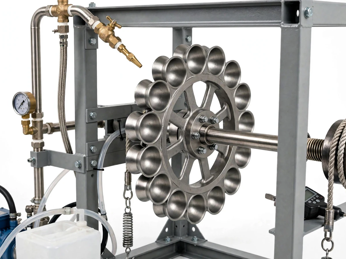
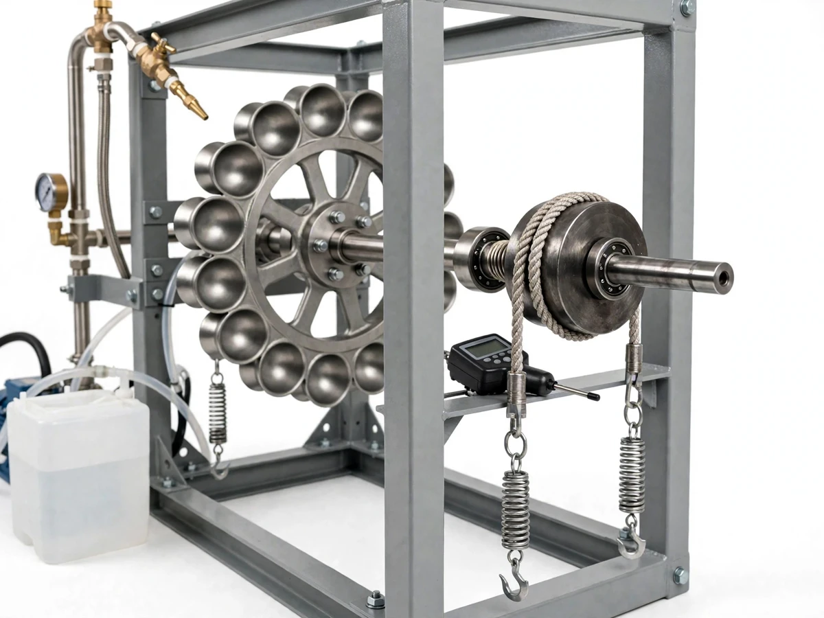
This Pelton wheel turbine test rig studies how a high-head water jet drives an impulse turbine and how its performance changes with nozzle opening and brake load. A centrifugal pump feeds water from a supply tank through a spear-valve nozzle, forming a compact jet that strikes the double-cup buckets of the Pelton wheel and spins its shaft. The shaft carries a rope-brake dynamometer, so the load can be raised step by step while a pressure gauge, a pair of spring balances and a digital tachometer record the operating point. From those readings, students compute torque, brake power, hydraulic input power and efficiency, and plot the characteristic curves of the turbine. The rig therefore turns textbook impulse-turbine theory into a bench experiment: one nozzle setting and one load at a time, each with numbers that can be checked against the theory in the report.
The problem this rig addresses is that impulse-turbine theory is usually taught from diagrams, while the behaviour that matters in practice — how power rises and falls with load, and where efficiency peaks — can only be seen on a running machine. Without a test rig, a student cannot measure what a nozzle change does to jet velocity, or what a heavier brake load does to shaft speed. This rig closes that gap with a compact laboratory setup: a recirculating water loop, an adjustable nozzle and a brake dynamometer that together produce the full operating curves from a single bench experiment.
The pump feeds water from the tank to the nozzle on a recirculating loop.
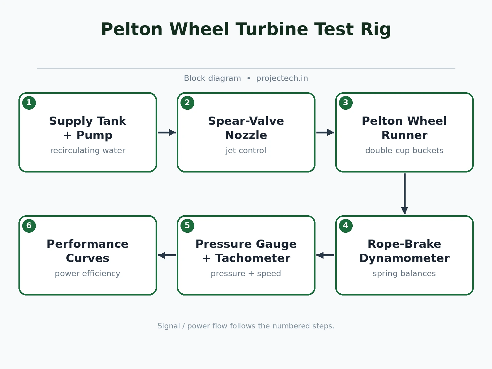
Follow the working sequence
How it works
The Pelton wheel turbine test rig works end to end as one energy-conversion chain: the pump raises water pressure, the spear-valve nozzle converts that pressure into a high-velocity jet, the jet strikes the Pelton buckets and spins the shaft, the rope brake loads the shaft, and the instruments turn that loaded running point into measured power. At each test point the operator sets a nozzle opening, tightens the brake to a chosen load, and reads nozzle pressure, both spring balances and shaft speed together. Torque follows from the balance difference and the drum radius, brake power follows from torque and speed, and hydraulic input power follows from pressure and flow. Efficiency is then brake power divided by input power. Repeating the sequence across nozzle openings and brake loads traces the turbine's characteristic curves.
- The centrifugal pump draws water from the supply tank and delivers it through the supply pipe to the spear-valve nozzle.
- The spear handwheel sets the nozzle opening, fixing the jet size, and the pressure gauge reads the nozzle inlet pressure for the run.
- The jet strikes the splitter ridge of a Pelton bucket, splits into two streams and reverses direction, pushing the runner around on its shaft.
- The shaft carries the brake drum, and the rope wound on the drum is tensioned by hand to apply a steady braking load.
- The two spring balances read the tight-side and slack-side rope tensions, and their difference gives the braking force at the drum.
- The digital tachometer reads shaft speed at the same moment, so load, pressure and speed describe one consistent operating point.
- Torque, brake power, input power and efficiency are calculated for the point from the balance readings, shaft speed, nozzle pressure and timed flow collection, and the run repeats at new nozzle openings and brake loads to build the curves.
Builder note from the build: set the nozzle so the jet meets the splitter ridge of the bucket squarely at the pitch circle, and check the strike by turning the runner slowly by hand before the first wet run. A jet that lands off the ridge spills to one side, shakes the runner and flattens the efficiency curve for no reason the instruments can explain. The mechanism behind the curves is first-principles and quotable: the Pelton wheel is an impulse turbine, so the jet gives up its momentum by reversing direction on the bucket, and the turning force on the shaft comes from that change in momentum, not from any pressure drop across the runner.
Tech stack:
- Pelton wheel · cast buckets
- Spear-valve nozzle · flow control
- Centrifugal pump · supply tank
- Rope-brake dynamometer · spring balances
- Bourdon pressure gauge · supply line
- Digital tachometer · shaft speed
- Mild-steel frame · shaft bearings
- Calculation sheet · performance curves
| Parameter | Value |
|---|---|
| Runner | Pelton wheel with cast double-cup buckets; pitch diameter 300 mm (design target) |
| Nozzle | Spear-valve nozzle with handwheel control; jet opening set by hand |
| Pump | Centrifugal pump on a recirculating loop (design target: delivery head 20 m) |
| Brake dynamometer | Rope brake on a shaft drum with a spring-balance pair (design target: drum diameter 200 mm) |
| Pressure measurement | Bourdon pressure gauge on the supply line (datasheet value: range 0 bar to 4 bar) |
| Speed measurement | Digital tachometer, non-contact (datasheet value: resolution 0.1 rpm) |
| Flow measurement | Timed collection into a measuring tank (procedure value: volume in litres, time in seconds) |
| Frame and bearings | Mild-steel angle frame with plummer-block shaft bearings |
| Test variables | Nozzle opening and brake load, both set by hand |
| Output | Torque in newton-metres, brake power in watts and efficiency in percent, plotted as characteristic curves |
Project features
The strongest capabilities of this Pelton wheel turbine test rig are spear-valve nozzle control that varies jet velocity without changing the pump, a rope-brake dynamometer that applies a measurable shaft load, and a complete instrument set — pressure gauge, spring balances and digital tachometer — that captures every operating point. Together these let a student run the full turbine test procedure on one bench: set a nozzle opening, apply a brake load, record speed and load, and repeat across the operating range. The recirculating supply loop keeps the experiment self-contained, since the same water returns to the tank after leaving the buckets. From the recorded readings, the report's characteristic curves — efficiency against speed, power against load, and torque against speed — follow directly, with no additional apparatus needed at all.
- [Spear-valve nozzle control — Implemented] A handwheel-driven spear inside the nozzle varies the jet opening, so jet velocity and flow change without touching the pump setting, letting one rig cover several operating points.
- [Double-cup Pelton wheel — Implemented] The runner carries cast double-cup buckets with a central splitter ridge, so the jet splits evenly and reverses direction, which is the impulse action the experiment measures.
- [Rope-brake dynamometer — Implemented] A rope wound on the brake drum with spring balances on both ends applies an adjustable shaft load, and the difference between the two balance readings gives the braking force for the torque calculation.
- [Pressure and speed instrumentation — Implemented] A Bourdon pressure gauge on the supply line reads the nozzle inlet pressure, and a digital tachometer reads shaft speed, so hydraulic input power and brake power come from the same operating point.
- [Recirculating water loop — Implemented] The pump draws from the supply tank and the discharge returns to the same tank, so the rig runs continuously on a bench without a mains water connection or a drain.
- [Characteristic-curve test procedure — Implemented] The build ships with a step-by-step test procedure and a calculation sheet for torque, brake power, input power and efficiency, so each run converts directly into report curves.
- [Adjustable nozzle and load settings — Configurable] Nozzle opening and brake load are set by hand at the rig, so the demonstrator can choose the test points that suit the laboratory session.
Optional customization, developed on request and not part of the base build: a second nozzle size for comparison runs, and a digital pressure transmitter in place of the Bourdon gauge. Future scope, not included: electronic data logging with automatic curve plotting.
What is included
- Working prototype: Pelton wheel rig with spear-valve nozzle, centrifugal pump, supply tank, rope-brake dynamometer, pressure gauge, spring balances and digital tachometer
- Test procedure document with step-by-step runs at varied nozzle openings and brake loads
- Calculation sheet for torque, brake power, input power and efficiency with a worked example
- Piping and assembly documentation, including nozzle alignment and brake setup
- Component list with part details for the runner, nozzle, pump, drum and instruments
- Project report PDF (background, impulse-turbine theory, methodology, test results and analysis)
- PPT presentation for final review
- Viva Q&A preparation document (impulse momentum, nozzle control, brake dynamometry, characteristic curves)
Limitations & prerequisites
- This is an academic laboratory prototype, not a power-station turbine: results demonstrate turbine behaviour at bench scale, not site performance.
- Efficiency depends on nozzle alignment and brake steadiness: a misaligned jet or a slipping rope flattens the curves, so the alignment check in the procedure must be done before wet runs.
- Flow measurement is manual timed collection: it suits steady operating points and cannot capture fast transients.
- The rig needs a level bench, a power point for the pump and a splash zone: it is a laboratory setup, not a portable demonstration unit.
- Spring-balance readings carry reading error: the procedure averages repeated readings at each point rather than trusting a single glance.
- The brake drum heats under sustained load: long runs at high load need cooling pauses, as noted in the procedure.
- Water splashes from the buckets: the test area needs a splash tray or drainage, which the laboratory must provide.
Frequently Asked Questions
What does the rig measure?
The rig measures shaft speed, brake load, nozzle pressure and flow at each operating point, and those readings convert into torque, brake power, hydraulic input power and efficiency, so the student plots full characteristic curves instead of reporting a single running point. Speed comes from the digital tachometer, load from the spring-balance pair, pressure from the Bourdon gauge, and flow from timed collection into the measuring tank.
Is this project suitable for a final-year project?
Yes, it fits Mechanical Engineering final-year programmes because it combines fluid machinery theory with a hands-on test procedure, measured operating curves and a calculation chain from raw readings to efficiency that a reviewer can follow step by step in the report. It demonstrates impulse-turbine theory, nozzle control, brake dynamometry and performance-curve analysis in one bench experiment, and the report carries real test data rather than textbook values alone.
How is torque measured with a rope brake?
Torque comes from the rope brake: the rope wound on the brake drum pulls harder on one spring balance than the other, and the difference between the two balance readings, multiplied by the drum radius, gives the braking torque on the shaft. Tightening the rope raises the load, so each operating point pairs one torque value with one shaft speed from the tachometer.
What does the nozzle control change?
Moving the spear inside the nozzle changes the jet opening, which changes the jet velocity and the flow rate, so one pump setting still yields several distinct operating points with different speeds, loads and efficiencies to compare in the report. A narrow opening gives a faster, thinner jet, while a wider opening passes more water at lower velocity, and the curves show which setting the turbine prefers.
Can the project be customized?
Yes, within realistic limits: a second nozzle size can be supplied for comparison runs, the Bourdon gauge can be replaced with a digital pressure transmitter, and the test procedure can be adapted to the laboratory session's time and bench space. Electronic data logging with automatic curve plotting is future scope and is not part of the base build, so it would be scoped as separate work.
What does the rig need in the laboratory?
The rig needs a level bench, a power point for the pump, a water supply for the first fill, and a splash tray or floor drainage, since the buckets throw water clear of the runner while the rig is running. No mains water connection or drain line is needed during runs, because the loop recirculates the same water from the supply tank.
Components & software requirements
- Pelton wheel · cast buckets
- Spear-valve nozzle · flow control
- Centrifugal pump · supply tank
- Rope-brake dynamometer · spring balances
- Bourdon pressure gauge · supply line
- Digital tachometer · shaft speed
- Mild-steel frame · shaft bearings
- Calculation sheet · performance curves
Delivery information
Built-to-order project. Delivery timeline is shared after order confirmation based on current queue.
Support terms
Complete documentation, setup guide, and viva preparation included. Support for setup and explanation provided.
Download free synopsis (PDF)
Enter your name and WhatsApp number — the synopsis PDF downloads immediately. We may send occasional project updates on WhatsApp; no spam.