
More project photos (2)
The problem
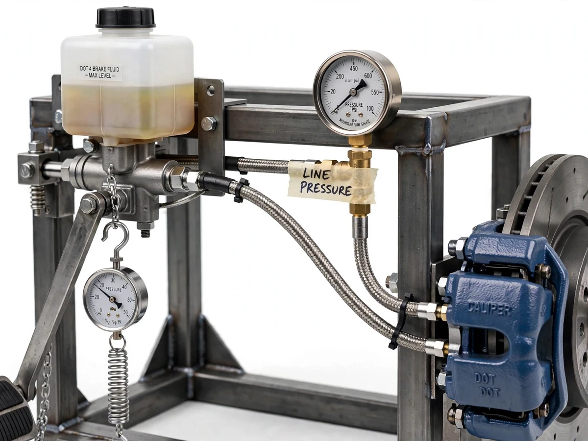
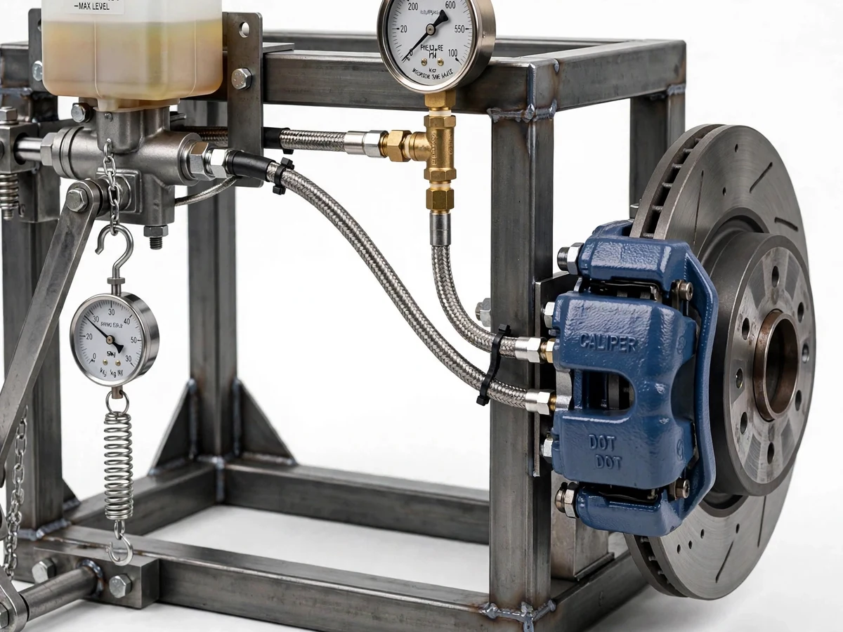
Every driver trusts that a light foot on the pedal becomes tonnes of clamping force at the disc — hydraulic advantage doing its quiet work through the master cylinder, the lines and the caliper pistons. In the classroom this is a formula: force times area ratio. In the lab it is almost never measured, because real brake systems are sealed, safety-critical assemblies that students cannot instrument. The gap is a dedicated, safe, open test rig where the whole chain is visible and every variable is measurable: pedal force in, line pressure through the system, clamping behavior out. This project builds it: a master cylinder actuated by a lever-type pedal with a spring-scale/load-cell force input, rigid lines to a brake caliper on a rotor disc, a bourdon-tube pressure gauge teed into the line, and a frame that holds everything rigid for repeatable tests. The student varies pedal force, reads pressure, and plots the system's actual pressure-vs-force characteristic against theory.
How it works
- The student bleeds the system per the procedure until the pedal is firm — no compressible air in the lines.
- A known force is applied to the pedal through the spring scale/load cell; the lever multiplies it into the master-cylinder pushrod.
- The master cylinder pressurizes the brake fluid; pressure transmits equally through the lines (Pascal's law).
- The bourdon gauge teed into the line reads the live hydraulic pressure; the caliper pistons clamp the rotor with force proportional to pressure times piston area.
- The student records paired readings (pedal force, line pressure) across a stepped force series.
- The data is plotted against the theoretical pressure from the bore-area ratios, and the deviation is analyzed honestly in the report.
Tech stack:
- Brake master cylinder with reservoir
- Pedal lever assembly with pivot and return spring
- Brake caliper + rotor disc
- Bourdon-tube hydraulic pressure gauge (teed into line)
- Spring scale / load cell for pedal-force input
- Steel-braided / rigid brake lines with fittings
- Welded steel test frame
- Brake fluid, bleed kit and service tools
- Test procedure with data-logging sheets
| Parameter | Value |
|---|---|
| System | Master cylinder → hydraulic lines → caliper + rotor (real brake hardware) |
| Input | Pedal lever with spring-scale/load-cell force measurement |
| Measurement | Bourdon pressure gauge teed into line; optional transducer for logging |
| Theory check | Measured pressure vs Pascal's-law prediction from bore areas |
| Frame | Rigid steel test frame holding cylinder, caliper and rotor in alignment |
| Service | Full bleed procedure included; fluid specified in documentation |
| Results | All pressure/force figures measured by the student; no claimed values at build |
Project features
- [Master cylinder + pedal lever] A real brake master cylinder driven by a pivoted pedal lever; the lever ratio is a documented, measurable part of the mechanical advantage chain.
- [Live pressure gauge] A bourdon-tube pressure gauge teed into the hydraulic line shows line pressure in real time as the pedal is pressed.
- [Caliper and rotor assembly] A brake caliper gripping a rotor disc completes the real system chain — students see clamping happen as pressure rises.
- [Measured pedal force input] Pedal force is applied through a spring scale or load cell, so every test point pairs a known input force with a gauge pressure reading.
- [Bleed and service procedure] The kit includes the proper brake-fluid bleeding procedure — because air in the lines is the classic reason student rigs read wrong, and the report should say so.
- [Theory-vs-measurement plots] The procedure guides the student to plot measured pressure against the Pascal's-law prediction from cylinder and caliper bore areas.
- [Rigid test frame] A welded/bolted steel frame holds the cylinder, caliper and rotor in fixed alignment so tests are repeatable across runs.
What is included
- Working brake-pressure test rig (cylinder, pedal, lines, caliper, rotor, gauge, frame)
- Fabrication drawings and assembly documentation
- Hydraulic schematic of the test circuit
- Bleed and service procedure
- Stepped test procedure with data-logging sheets
- Component list with ratings
- Project report PDF (brake hydraulics theory, rig design, methodology, student's plots)
- PPT presentation for final review
- Viva Q&A preparation document (Pascal's law, hydraulic advantage, brake system basics)
- Setup and demonstration guide
Limitations & prerequisites
- This is a static test rig, not a vehicle brake system: the rotor does not spin under load and no stopping-distance or fade claims can be made — the report scopes it as a pressure/transmission study.
- All performance figures are the student's own gauge readings; bore wear, seal condition and bleed quality all affect results, and the report must present them as measured.
- Brake fluid is hygroscopic and corrosive to paint; handling, spill and disposal notes are part of the safety documentation and must be followed.
- The gauge reads line pressure at its tee point; it does not measure caliper clamping force directly — that is derived, and the derivation's assumptions are stated.
- Air in the lines invalidates every reading; the bleed procedure is not optional, and the report should include a "with air vs bled" comparison as honest data.
Frequently Asked Questions
What does the rig actually measure?
Pedal input force (spring scale/load cell) against hydraulic line pressure (bourdon gauge) — the complete input-to-pressure chain of a brake system, plotted against theory.
Are real brake parts used?
Yes — a genuine master cylinder, caliper and rotor with proper brake lines, mounted on a rigid test frame. That is what makes the Pascal's-law verification meaningful.
Why is bleeding so important?
Air compresses; fluid doesn't. Any air in the lines makes the pedal spongy and the pressure readings wrong — the kit includes the full bleed procedure.
Can it test stopping distance?
No. The rotor is static; this rig studies pressure transmission and hydraulic advantage, not dynamic braking performance.
Is brake fluid dangerous?
It is hygroscopic and damages paint; the safety sheet covers handling, spill cleanup and disposal — follow it.
Is this project suitable for a final-year project?
Yes — for Mechanical and Automobile programs. It turns a textbook formula into a measured, plotted, honestly-analyzed experiment on real hardware. Suitable for B.E./B.Tech final-year projects in Mechanical and Automobile engineering.
Components & software requirements
- Brake master cylinder with reservoir
- Pedal lever assembly with pivot and return spring
- Brake caliper + rotor disc
- Bourdon-tube hydraulic pressure gauge (teed into line)
- Spring scale / load cell for pedal-force input
- Steel-braided / rigid brake lines with fittings
- Welded steel test frame
- Brake fluid, bleed kit and service tools
- Test procedure with data-logging sheets
Delivery information
Built-to-order project. Delivery timeline is shared after order confirmation based on current queue.
Support terms
Complete documentation, setup guide, and viva preparation included. Support for setup and explanation provided.