
More project photos (2)
The problem
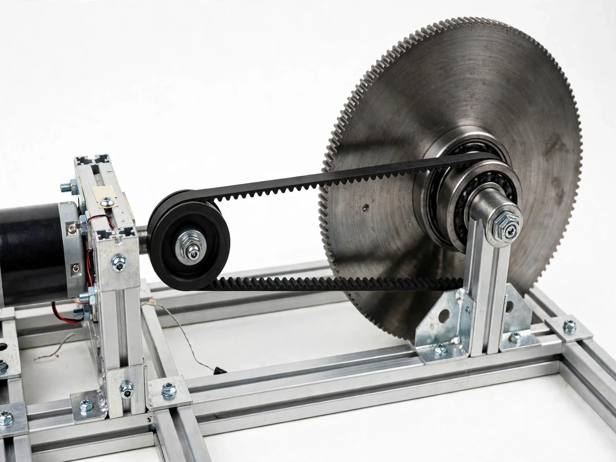
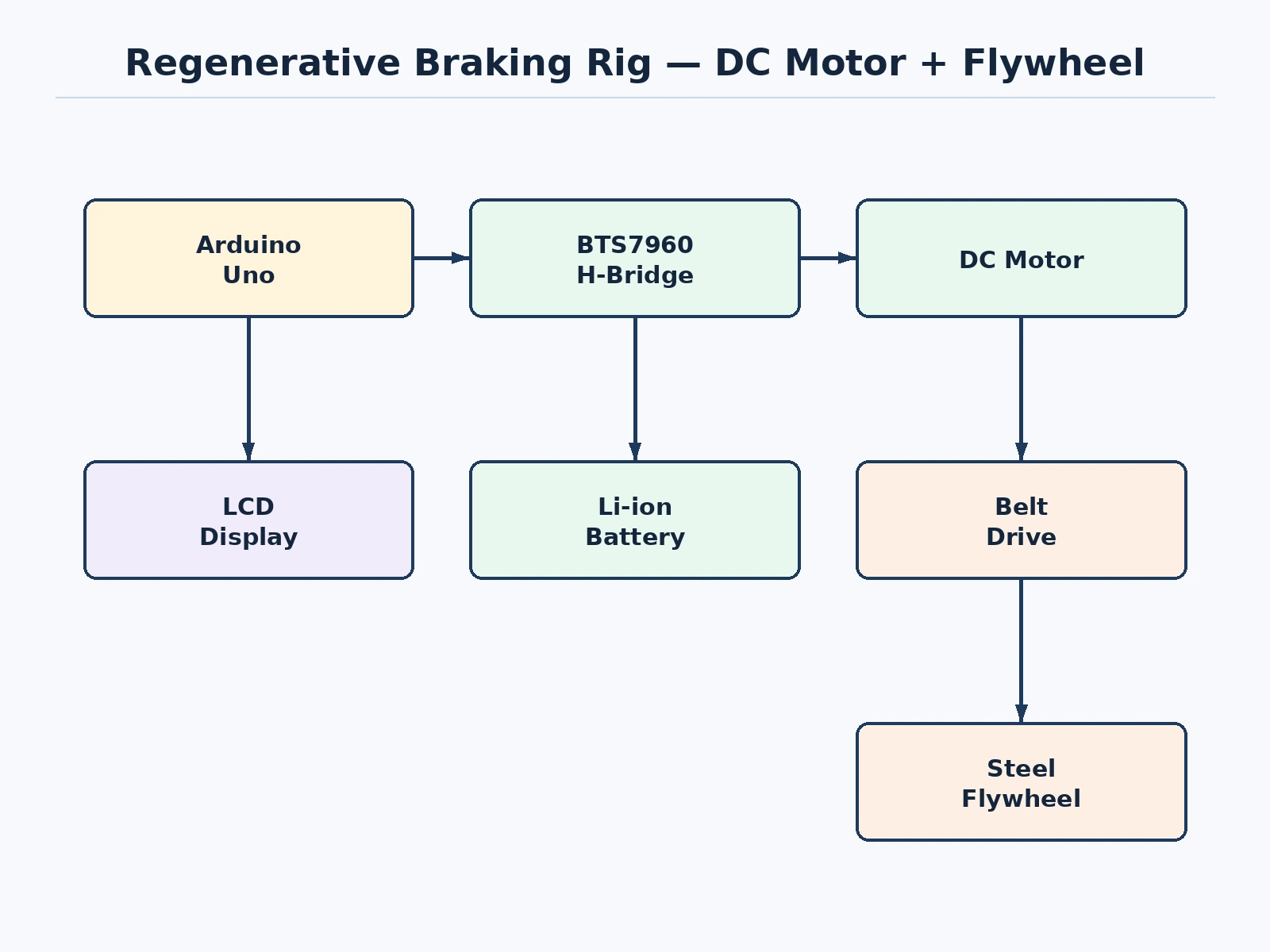
When an electric vehicle brakes, its motor controller reverses the power flow: the motor becomes a generator, the car's kinetic energy becomes electrical energy, and the battery recharges instead of the energy being wasted as heat in brake pads. Students hear this in EV courses but rarely see the energy actually flow back. This project makes it visible on a bench rig: a DC motor on an aluminum frame is belt-coupled to a heavy flywheel disc. The motor spins the flywheel up (motoring mode); then the controller switches to generator mode, the flywheel drives the motor as a generator, and the generated current flows into a Li-ion battery pack through the driver — with speed and regenerated current shown live on an LCD and a multimeter. The student measures spin-up energy versus recovered energy and computes the round-trip efficiency themselves.
Switches the H-bridge between motoring and generating modes and drives the LCD.
Follow the working sequence
How it works
- The student assembles the aluminum-frame rig: DC motor, belt drive, flywheel disc on bearing blocks, driver board, battery pack, Arduino and LCD per the guide.
- In motoring mode the driver powers the DC motor, spinning the flywheel up to the target speed; the LCD shows the rising RPM.
- The student switches to braking mode: the driver reconfigures the bridge so the spinning motor acts as a generator loaded by the battery-charging path.
- The flywheel's kinetic energy converts to electrical energy — the LCD and multimeter show the charging current while the flywheel visibly slows down.
- The student logs speed decay and charging current over the braking run, then computes recovered energy versus the spin-up energy input.
- The efficiency number and the energy-flow discussion form the results chapter, all from the student's own measurements.
Tech stack:
- DC motor (generator-capable) with belt drive
- Steel flywheel disc on bearing blocks
- BTS7960-class H-bridge motor driver
- Arduino Uno (ATmega328P) with mode-control firmware
- 3S Li-ion battery pack with protection circuit
- LCD for live speed and regenerated-current display
- Multimeter for independent current measurement
- Aluminum extrusion frame with fasteners
| Parameter | Value |
|---|---|
| Flywheel | Steel disc, approximately 200 mm diameter (design) |
| Drive ratio | Approximately 1:3 motor-to-flywheel step-up (design) |
| Motor | 12 V DC, approximately 3000 rpm class (design) |
| Battery | 3S Li-ion, approximately 2200 mAh with protection (design) |
| Regenerated current | Approximately 0.3–0.8 A typical during braking (expected) |
| Expected round-trip efficiency | Approximately 30–50% (expected, measured by student) |
| Frame | Aluminum extrusion bench rig (design) |
Project features
- [Motor/generator changeover] A BTS7960-class H-bridge driver run by the Arduino switches the DC machine between motoring (spin up the flywheel) and generating (brake the flywheel, charge the battery).
- [Heavy flywheel energy store] A steel flywheel disc on bearings stores the kinetic energy visibly — the audience watches it spin down as the battery charges, which makes the energy transfer tangible.
- [Live energy instrumentation] An LCD shows shaft speed and regenerated current in real time; a multimeter in series with the battery gives an independent current reading for the report.
- [Battery charge management] The generated output charges a 3S Li-ion pack through the driver's current-limited path with the pack's protection circuit guarding against overcharge.
- [Belt drive with real inertia] A toothed belt couples motor to flywheel with a step-up ratio, so the flywheel stores meaningful energy at safe bench speeds.
- [Round-trip efficiency procedure] A documented procedure measures electrical energy in (spin-up) and energy recovered (braking) from logged speed and current, so the student computes efficiency from their own data.
- [Brake-force control] The generator loading (electrical braking torque) is adjustable in firmware, demonstrating how EVs blend regenerative and friction braking.
What is included
- Working regenerative braking rig (frame, motor, flywheel, driver, battery, instrumentation)
- Arduino mode-control firmware with adjustable brake loading
- Energy-measurement and efficiency-computation procedure
- Mechanical assembly guide with wiring diagram
- Project report PDF (regenerative braking theory, rig design, measured efficiency procedure)
- PPT presentation for final review
- Viva Q&A preparation document (motor-as-generator, energy recovery, efficiency losses)
Limitations & prerequisites
- A bench demonstrator: the recovered energy is small (fractions of a watt-hour) — it proves the principle, it does not power anything useful.
- Round-trip efficiency is modest (expected approximately 30–50%) because of belt, bearing, driver and battery losses; the report discusses each loss honestly.
- The Li-ion pack must never be overcharged or shorted; the protection circuit and the manual's safety rules are mandatory.
- The flywheel stores real kinetic energy: the guard and the manual's spin-up limits must be respected.
- Efficiency depends on speed, load and battery state — the student's measured value, not a claimed figure, is the report's result.
- Not a vehicle system: road-load, blended friction braking and thermal management of real EV regen are noted as beyond scope.
Frequently Asked Questions
Where does the "regenerated" energy actually go?
Into the 3S Li-ion battery pack: the generator-mode current flows through the driver into the pack, and the multimeter shows it live. The flywheel visibly slows as its kinetic energy becomes charge.
Why is the efficiency only 30–50%?
Every conversion loses energy — belt friction, bearing drag, copper and iron losses in the machine, driver switching losses, battery charge inefficiency. The procedure has the student account for each, which is excellent viva material.
How is this different from just shorting the motor to brake it?
Shorting (dynamic braking) dumps the energy as heat in the windings. Regenerative braking routes it into the battery instead — same braking effect, recovered energy.
Can the braking force be adjusted?
Yes — the firmware sets the generator loading, which sets the electrical braking torque. Light loading gives gentle, long braking; heavy loading stops the flywheel fast with higher peak current.
Is the battery safe during charging?
The pack has a protection circuit (overcharge/overcurrent), the driver current-limits the charge path, and the manual's safety rules cover handling. Mains power is not involved anywhere.
Is this project suitable for a final-year project?
Yes — for Electrical and Mechanical programs. It demonstrates electric machines, energy conversion, power electronics and experimental efficiency measurement. Suitable for B.E./B.Tech final-year projects in Electrical and Mechanical.
Components & software requirements
- DC motor (generator-capable) with belt drive
- Steel flywheel disc on bearing blocks
- BTS7960-class H-bridge motor driver
- Arduino Uno (ATmega328P) with mode-control firmware
- 3S Li-ion battery pack with protection circuit
- LCD for live speed and regenerated-current display
- Multimeter for independent current measurement
- Aluminum extrusion frame with fasteners
Delivery information
Built-to-order project. Delivery timeline is shared after order confirmation based on current queue.
Support terms
Complete documentation, setup guide, and viva preparation included. Support for setup and explanation provided.
Download free synopsis (PDF)
Enter your name and WhatsApp number — the synopsis PDF downloads immediately. We may send occasional project updates on WhatsApp; no spam.