
More project photos (2)
The problem
Power supplies, chargers and batteries are only as good as their behavior under load: voltage droop, current limit and capacity must all be measured with something that draws a known, steady current. Commercial electronic loads cost thousands of rupees and student labs usually settle for resistor banks that cannot hold a constant current as voltage falls. Building a proper programmable load is a genuine power-electronics exercise: the MOSFET must be driven in its linear region (not as a switch), an op-amp feedback loop must compare a setpoint against a shunt-resistor measurement, and the heat the MOSFET dumps must be managed by a heatsink and fan with thermal protection. This project implements exactly that loop around an IRFZ44N on a finned heatsink, an LM358 error amplifier, an Arduino Nano that generates the setpoint from a rotary encoder, and an LCD that reports the operating point. Constant-current and constant-power modes make it useful for real bench work such as supply testing and battery discharge-capacity checks.
The supply or battery being loaded, up to 30 V DC on the DC IN terminals.
Follow the working sequence
How it works
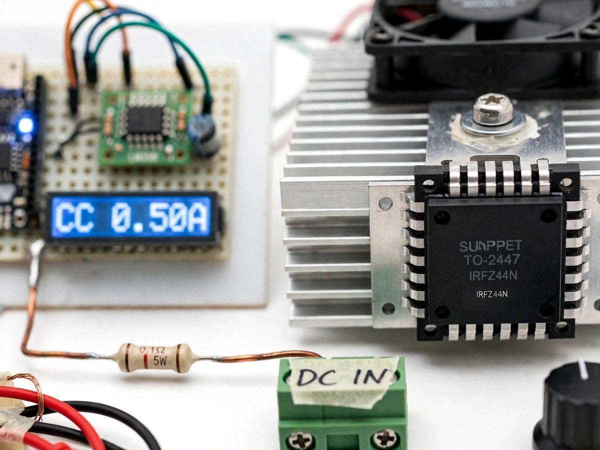
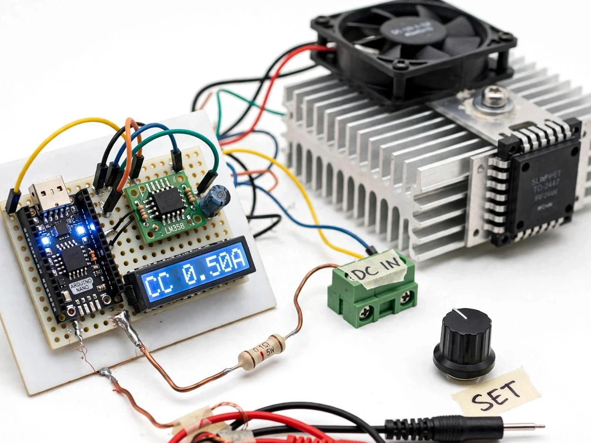
- The device under test (supply or battery, up to 30 V DC design maximum) connects to the green DC IN terminal block; the IRFZ44N MOSFET, shunt resistor and terminal block form the sink path to ground.
- The LM358 amplifies the voltage across the 0.1 ohm 5 W shunt resistor by roughly 10x, giving the Arduino a 0–5 V signal representing 0–5 A of load current.
- The Arduino reads the rotary encoder, generates the setpoint as a filtered PWM voltage, and the LM358 drives the MOSFET gate so the shunt voltage tracks the setpoint — holding current constant in CC mode.
- In CP mode the Arduino samples input voltage and load current, computes power, and nudges the setpoint each cycle to hold absorbed power at the target (design up to 50 W).
- The NTC thermistor reports heatsink temperature; the fan starts above about 50 C (design target) and the firmware cuts the load if temperature keeps climbing toward 85 C (design target).
- In battery test mode the unit sinks the set CC current and integrates ampere-hours until the input voltage reaches the configured cutoff, then latches off and shows the measured capacity on the LCD.
- A buyer-run calibration with an ordinary multimeter trims two gain constants in firmware so displayed current and power match measured values.
Tech stack:
- IRFZ44N power MOSFET on finned aluminium heatsink with 12 V cooling fan
- LM358 dual op-amp (current-loop error amplifier + shunt signal conditioning)
- Arduino Nano (ATmega328P) — setpoint generation, modes, protection logic
- 0.1 ohm 5 W shunt resistor for load-current sensing
- 16x2 character LCD + rotary encoder with push-button
- NTC thermistor for heatsink temperature monitoring
- Green screw terminal block for the DC input under test
- 12 V DC supply (fan + control rails)
| Parameter | Value |
|---|---|
| Maximum input voltage | 30 V DC (design limit) |
| Constant-current range | 0 to 5.00 A (design target), 0.05 A setpoint steps |
| Constant-power range | Up to 50 W (design target, with cooling fan running) |
| MOSFET (linear mode) | IRFZ44N, 55 V / 49 A datasheet ratings (used far below switching limits) |
| Current sensing | 0.1 ohm 5 W shunt, LM358 amplified to 0–5 V for the Arduino ADC |
| Thermal control | Fan on above ~50 C, load cutout approaching ~85 C (design targets) |
| Battery discharge test | CC discharge with voltage cutoff; capacity integrated in ampere-hours (design target) |
| Display | 16x2 LCD: mode, set current, actual current, power, temperature |
| Control supply | 12 V DC for fan and control electronics |
| Board style | Hand-built perfboard prototype with terminal-block input |
Project features
- [Constant-current (CC) mode] Dial any setpoint from 0 to 5.00 A on the rotary encoder; the op-amp loop holds the sink current steady as the source voltage varies, with the live current on the LCD.
- [Constant-power (CP) mode] The Arduino multiplies measured voltage by current and trims the setpoint so the load absorbs a fixed power target (up to the 50 W design limit) regardless of input voltage.
- [Op-amp current feedback loop] An LM358 error amplifier drives the IRFZ44N gate from the difference between the setpoint and the shunt-resistor voltage — a classic linear regulator topology, explained step by step for the viva.
- [Rotary encoder setpoint + LCD UI] A click encoder adjusts the setpoint in 0.05 A steps; the 16x2 LCD shows mode, set current, actual current, absorbed power and heatsink temperature.
- [Overtemperature protection] An NTC thermistor on the heatsink spins up the 12 V fan past the fan-on threshold and cuts the load if the sink keeps rising, so a MOSFET cannot cook itself during long tests.
- [Battery discharge test mode] Select discharge mode, set the cutoff voltage, and the Arduino integrates current over time until cutoff, reporting the battery's usable capacity in ampere-hours on the LCD.
- [Calibration procedure] A buyer-run calibration against a multimeter trims the shunt gain and voltage divider so the displayed current and power readings track the real values.
What is included
- Working hardware prototype (MOSFET + heatsink + fan module, control board, LCD, encoder, terminal block)
- Arduino firmware (CC mode, CP mode, battery discharge test, thermal protection)
- Circuit schematic and wiring photographs for replication
- Heatsink and thermal design notes (why the fan and cutout are sized as they are)
- Buyer-run calibration procedure against a multimeter
- Project report PDF (linear-mode MOSFET theory, feedback loop design, thermal analysis, test procedures)
- PPT presentation for final review
- Viva Q&A preparation document (MOSFET linear region, op-amp loops, shunt sensing, SOA, thermal derating)
Advantages
- Constant-current mode from 0 to 5.00 A in 0.05 A steps, plus constant-power mode up to 50 W: an LM358 op-amp feedback loop drives the IRFZ44N gate from the difference between the setpoint and the 0.1 ohm shunt-resistor voltage — a classic linear-regulator topology explained step by step for the viva.
- The MOSFET runs in its linear region, not as a switch — exactly what a programmable load needs for smoothly adjustable sink current — with a finned heatsink and 12 V cooling fan sized for the heat it dumps.
- Bench-useful battery discharge test: sinks a fixed CC current and integrates ampere-hours until the configured voltage cutoff, reporting the battery's usable capacity on the 16x2 LCD alongside mode, set/actual current, power and heatsink temperature.
- Overtemperature protection from an NTC thermistor: the fan starts above ~50°C and the firmware cuts the load toward ~85°C; a buyer-run calibration against an ordinary multimeter trims shunt gain and voltage divider so displayed readings track real values.
Disadvantages
- Maximum dissipation is about 50 W with the fan running — a bench instrument, not a high-power load bank; sustained testing near the limit needs airflow.
- The MOSFET's safe operating area narrows in linear mode at high voltage drop — the 30 V / 50 W design limits keep it inside the derated SOA; pushing beyond risks device failure.
- Displayed current accuracy is approximately ±2% after the buyer-run calibration — a student bench instrument, not lab calibration-grade equipment — and there is no PC logging software; readings are shown on the LCD and noted manually.
- DC only, up to 30 V: it cannot sink AC and must never be connected to mains; multi-cell high-voltage battery packs are out of scope.
Limitations & prerequisites
- Maximum dissipation is about 50 W with the fan running (design target) — this is a bench instrument, not a high-power load bank; sustained testing near the limit needs airflow.
- The MOSFET runs in linear mode, so its safe operating area narrows at high voltage drop — the 30 V / 50 W design limits keep it inside the derated SOA; pushing beyond risks device failure.
- Displayed current accuracy is approximately ±2% after the buyer-run calibration (design target) — this is a student bench instrument, not lab calibration-grade equipment.
- Battery discharge tests are limited to 30 V inputs; multi-cell high-voltage packs are out of scope.
- DC only — the unit cannot sink AC and must never be connected to mains.
- There is no PC logging or graphing software; readings are shown on the LCD and noted manually.
Frequently Asked Questions
How does the current stay constant when the source voltage changes?
The LM358 op-amp continuously compares the shunt-resistor voltage (actual current) against the setpoint voltage and drives the MOSFET gate to erase the difference. If the source voltage rises, the loop turns the MOSFET down to keep current fixed; if it falls, the loop opens the gate wider.
Why is a MOSFET run in linear mode instead of switching?
Switching gives only on or off; an electronic load must sink a partial, smoothly adjustable current. In the linear (saturation) region the MOSFET acts like a voltage-controlled resistor, which is exactly what a programmable load needs — at the cost of all the dropped power becoming heat, hence the heatsink and fan.
What is the battery discharge test good for?
It measures a battery's usable capacity: the load sinks a fixed current and the Arduino integrates ampere-hours until the battery voltage reaches the cutoff you set. Comparing the result against the printed rating is a strong experimental result for the report.
How hot does the heatsink get?
It depends on dissipated power — at the 50 W design limit the sink gets properly hot, which is why the fan starts around 50 C and the firmware cuts the load toward 85 C. Long full-power tests should be done with airflow and the cutout left enabled.
Can I test my phone charger or a solar panel with it?
A DC phone charger or a small DC supply up to 30 V is fine — that is exactly what CC mode is for. A solar panel works too since it is a DC source, but its output varies with light, so CP mode is the better choice there.
Is this project suitable for a final-year project?
Yes — for Electrical and Electronics programs. It combines power electronics (linear MOSFET control), analog design (op-amp feedback, shunt sensing), embedded firmware (modes, protection, capacity integration) and thermal engineering in one demonstrable bench instrument. Suitable for B.E./B.Tech final-year projects in Electrical and Electronics.
Components & software requirements
- IRFZ44N power MOSFET on finned aluminium heatsink with 12 V cooling fan
- LM358 dual op-amp (current-loop error amplifier + shunt signal conditioning)
- Arduino Nano (ATmega328P) — setpoint generation, modes, protection logic
- 0.1 ohm 5 W shunt resistor for load-current sensing
- 16x2 character LCD + rotary encoder with push-button
- NTC thermistor for heatsink temperature monitoring
- Green screw terminal block for the DC input under test
- 12 V DC supply (fan + control rails)
Delivery information
Built-to-order project. Delivery timeline is shared after order confirmation based on current queue.
Support terms
Complete documentation, setup guide, and viva preparation included. Support for setup and explanation provided.
Download free synopsis (PDF)
Enter your name and email — the synopsis PDF downloads immediately. We may send occasional project updates; no spam, unsubscribe anytime.