
More project photos (2)
The problem
Street lights are usually maintained through complaint-driven rounds: a fault is found only after a citizen reports it or a maintenance crew happens to pass by. That gap means a failed lamp can leave a stretch of road dark for days, which affects road safety and public confidence in the municipal lighting network. Utilities that do monitor their network typically rely on crew visits or expensive SCADA retrofits, neither of which fits the budget of a small municipality. This project demonstrates a practical middle path — a low-cost fault-detection node built around an Arduino Nano that continuously measures the current drawn by a light point with an ACS712 current-sensor module and reports anomalies over a SIM800L GSM module as SMS messages to the control room. Three fault conditions are covered: lamp failure (current drops near zero at night), lamp glowing in daylight (current present when it should be off), and abnormal current patterns that suggest cable theft or tampering. The system is built and demonstrated at bench scale with a model street light so it can be shown and examined as a final-year project.
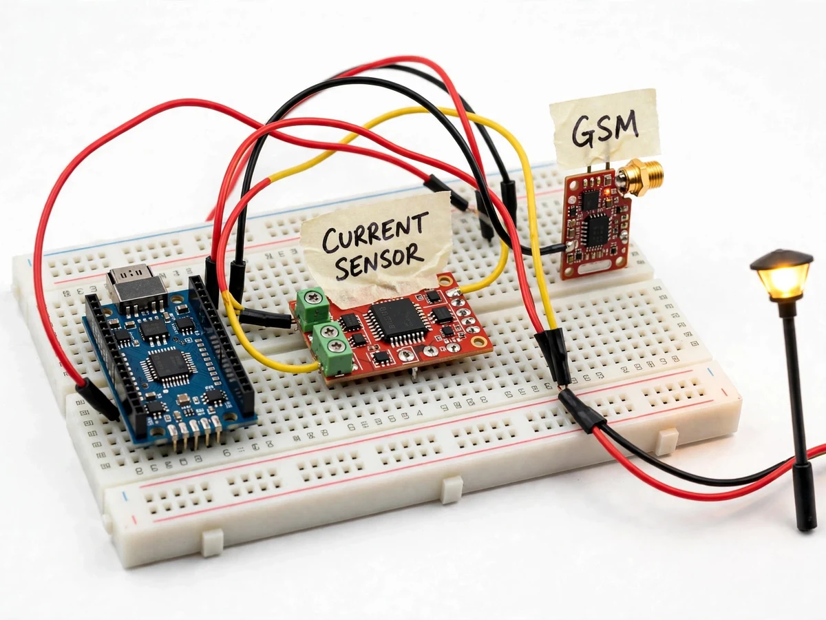
12 V demonstrator lamp standing in for one street light point.
Follow the working sequence
How it works
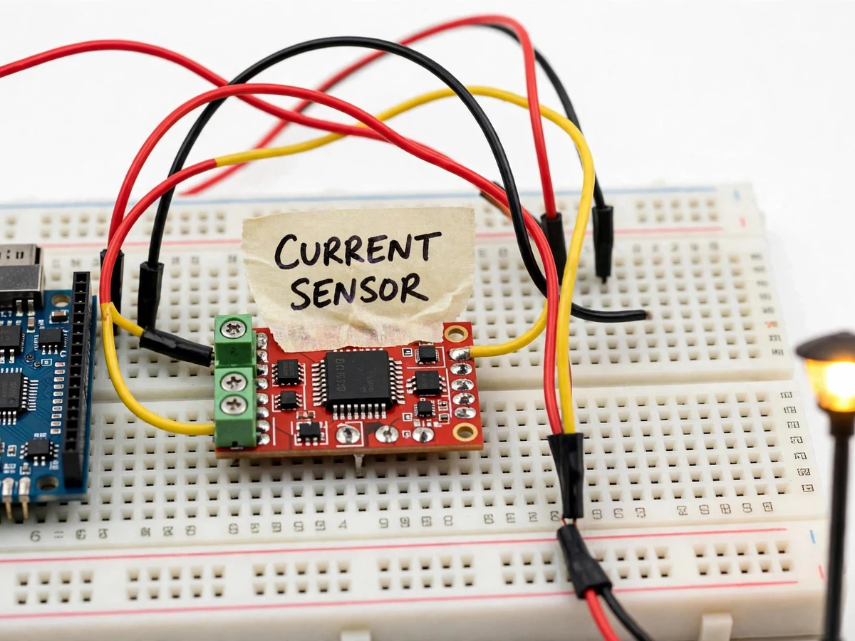
- A 12 V lamp load on the demonstrator model stands in for one street light; the ACS712-5A sensor module sits in series with the lamp circuit and outputs a voltage proportional to the current.
- The Arduino Nano reads the sensor output on an analog pin, samples it over a short window and converts it to a current value using the ACS712 sensitivity (approximately 185 mV per ampere for the 5A variant).
- The firmware checks the current operating schedule: during the ON window it expects current within the configured healthy band; during the OFF window it expects near zero.
- Three rules classify the reading: zero current in the ON window = lamp failure; significant current in the OFF window = daylight glowing; sudden large deviation from the learned baseline = tamper/theft suspicion.
- On any fault classification, the controller composes a message with the node ID, fault type and a timestamp and passes it to the SIM800L module.
- The SIM800L, registered on the GSM network with a standard SIM card, sends the SMS to the stored control-room numbers and the node logs the event locally.
- The on/off schedule, current thresholds and phone numbers are stored in EEPROM and can be reconfigured through serial commands without recompiling the firmware.
Tech stack:
- Arduino Nano (ATmega328P)
- ACS712-5A Hall-effect current-sensor module
- SIM800L GSM module with standard SIM card
- Embedded C (Arduino framework), EEPROM configuration
- 12 V DC bench lamp demonstrator + relay switching
- Breadboard prototyping with screw-terminal wiring
| Parameter | Value |
|---|---|
| Controller | Arduino Nano, ATmega328P, 16 MHz (ATmega datasheet) |
| Current sensor | ACS712ELCTR-5A, ±5 A range, ~185 mV/A sensitivity (datasheet) |
| Sensor accuracy | ±1.5% typical at 25°C (ACS712 datasheet value, not measured) |
| GSM module | SIM800L, quad-band 850/900/1800/1900 MHz (module datasheet) |
| GSM supply | 3.4–4.4 V, peak bursts up to ~2 A — dedicated regulator required (datasheet) |
| Fault scan cycle | Configurable, design target 30–60 s per light point |
| Fault classes | Lamp failure, daylight glowing, tamper/theft indication |
| Alert channel | SMS to up to 3 stored numbers (configurable) |
| Demonstrator load | 12 V DC lamp model, 0.5–2 A depending on configuration |
| Power supply | 12 V DC adapter (bench), separate 4 V regulator for SIM800L |
Project features
- [Per-light current monitoring] An ACS712-5A current-sensor module continuously measures the current drawn by each light point; the firmware compares the reading against configured expected-current bands for the ON and OFF states.
- [Lamp-failure detection] When the night-state schedule expects current but the sensor reads near zero, the controller flags a lamp failure — burnt-out lamp, failed driver or loose connection — and reports it within the configured scan cycle.
- [Daylight-glowing detection] If current is detected during the scheduled off period, the system flags a lamp that is glowing in daylight, which wastes energy and usually points to a stuck relay or controller fault.
- [Theft and tampering indication] A sudden large drop or irregular current signature that does not match either fault pattern raises a separate tamper alert, useful for identifying cable theft or unauthorized tapping.
- [GSM SMS reporting] A SIM800L module sends a plain-text SMS to configured control-room numbers with the light-point ID, fault type and timestamp; the recipient list and messages are editable in firmware.
- [Scheduled monitoring] The firmware tracks a configurable on/off schedule so night and day fault conditions are evaluated against the correct expectation — the schedule can be matched to local sunset/sunrise or a timer relay.
- [Local fault indicator] An onboard LED/buzzer gives immediate local indication at the node for bench demonstration and field commissioning without waiting for an SMS.
What is included
- Assembled bench prototype: Arduino Nano, ACS712 sensor module, SIM800L GSM module, relay, breadboard wiring, model street light
- Complete firmware source with commented fault-detection logic and SMS routine
- Wiring diagram and pin-connection sheet
- Calibration and threshold-setting procedure (buyer-run)
- Project report PDF (background, current-sensing theory, GSM communication, methodology, results)
- PPT presentation for final review
- Viva Q&A preparation document (Hall-effect sensing, ADC sampling, AT commands, fault logic)
Limitations & prerequisites
- Demonstrated at bench scale with a 12 V model lamp; a real street-light deployment would need AC-rated sensing (current transformers), weatherproof enclosures and mains-isolation design — explicitly out of scope.
- The prototype monitors one light point; covering a road stretch needs one node per point plus a real addressing scheme, which is a deployment architecture decision.
- SIM800L needs a valid SIM with SMS balance and adequate network signal; rural dead zones delay or lose alerts — the module reports network registration status so this is observable.
- SMS latency depends on the carrier; delivery in seconds is typical but not guaranteed, so this is a maintenance aid, not a protection device.
- ACS712 ±1.5% is a datasheet typical figure; the report documents the buyer's own calibrated thresholds, not a measured accuracy claim for this build.
- Night/day scheduling uses a configured timer, not an astronomical clock or light sensor — a real deployment would add an LDR or RTC with sunrise/sunset logic (noted as future scope).
Frequently Asked Questions
How does current sensing detect a street-light fault?
A healthy lamp draws a predictable current when switched on. The ACS712 module measures that current continuously; if the controller expects the lamp on but reads near zero, the lamp has failed. If current appears during the scheduled off period, the lamp is glowing in daylight. Thresholds are configured during calibration.
Why GSM instead of Wi-Fi or LoRa?
Municipal light points are scattered across roads with no guaranteed Wi-Fi. GSM covers almost everywhere, SMS needs no data plan, and the SIM800L module is cheap and well documented — making it a realistic fit for a student build and for small municipalities.
Can it tell the difference between a failed lamp and a power cut?
The node reports loss of its own expected current; a full power cut also silences the node's own supply, which is itself informative. Distinguishing the two needs an upstream mains-presence signal — documented as a configurable extension in the report.
How many light points can one system monitor?
This prototype is a single-node demonstrator: one Arduino Nano + one ACS712 + one SIM800L covering one light point. The architecture scales by replicating the node per point, each reporting to the same control-room numbers.
What SIM and power does the GSM module need?
A standard 2G-capable SIM with SMS balance, and a dedicated 3.4–4.4 V supply able to deliver ~2 A bursts during transmission. Powering the SIM800L directly from the Arduino's 5 V rail causes resets under transmit load — the build uses a separate regulator, as the module datasheet requires.
Is this project suitable for a final-year project?
Yes — for Electrical and Electronics engineering programs. It combines sensor interfacing, ADC sampling, embedded decision logic and wireless alerting into a real municipal problem, with honest, explainable engineering throughout. Suitable for B.E./B.Tech final-year projects in Electrical and Electronics.
Components & software requirements
- Arduino Nano (ATmega328P)
- ACS712-5A Hall-effect current-sensor module
- SIM800L GSM module with standard SIM card
- Embedded C (Arduino framework), EEPROM configuration
- 12 V DC bench lamp demonstrator + relay switching
- Breadboard prototyping with screw-terminal wiring
Delivery information
Built-to-order project. Delivery timeline is shared after order confirmation based on current queue.
Support terms
Complete documentation, setup guide, and viva preparation included. Support for setup and explanation provided.
Download free synopsis (PDF)
Enter your name and email — the synopsis PDF downloads immediately. We may send occasional project updates; no spam, unsubscribe anytime.