
More project photos (3)
The problem
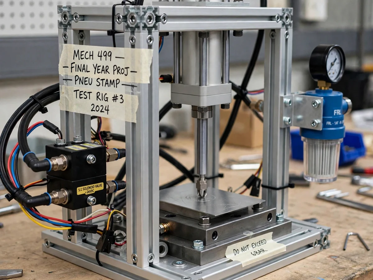
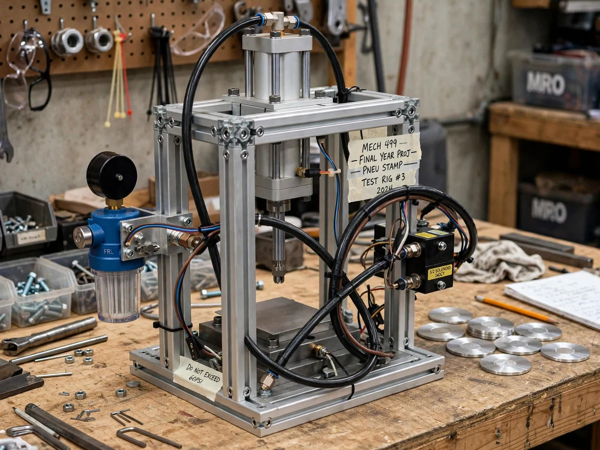
Small-batch marking and forming — stamping logos, serial marks or shallow patterns into metal blanks — is usually done on expensive hydraulic or mechanical presses that are overkill for a college lab or a small workshop. Pneumatics offers a middle path: shop air is cheap, cylinders are simple, and a single solenoid valve gives clean, repeatable two-position control of a double-acting cylinder. This project builds that idea into a benchtop stamping machine. A 5/2 solenoid valve routes regulated air from an FRL (filter-regulator-lubricator) unit to either side of a double-acting cylinder; the extending rod drives a punch onto a steel die plate holding a thin metal disc, and a push-button station fires each cycle. The frame is built from aluminum extrusion so the whole machine can be assembled, adjusted and disassembled with hand tools. Stamping force follows directly from bore area times pressure — a calculation the student performs and documents, with the regulator letting force be varied deliberately across trials. This is a built-to-order hardware project: the machine is assembled, plumbed and trial-stamped fresh for your order.
Presses the cycle button, places blanks and records pressure-vs-impression data.
Follow the working sequence
How it works
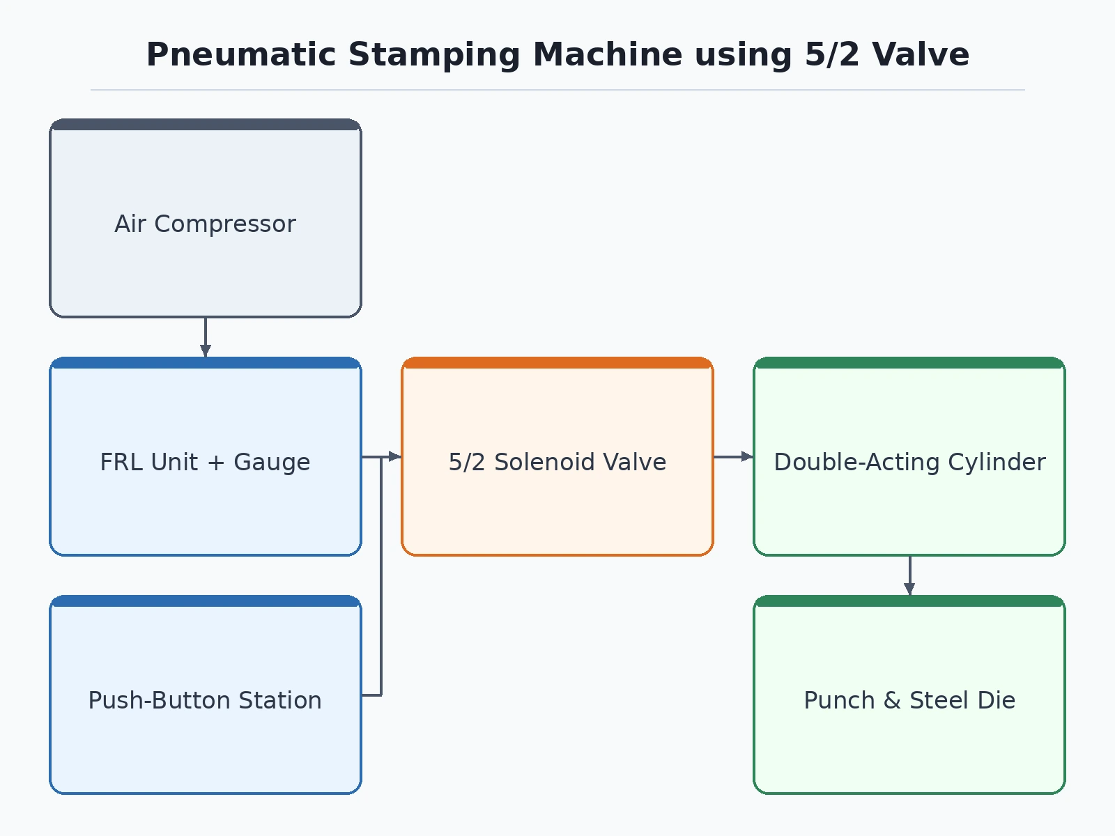
- An external compressor feeds the FRL unit, which filters the air and regulates it to the set pressure shown on the gauge.
- Pressing the cycle button energizes the 5/2 solenoid valve, shifting it so air flows to the cylinder's cap end.
- The piston rod extends, driving the punch down onto the metal disc on the die plate and stamping it.
- Releasing the button de-energizes the valve; its spring return shifts air to the rod end and retracts the punch.
- The stamped disc is removed, a fresh blank is placed, and the cycle repeats.
- Trials at different regulator pressures produce the pressure-vs-impression data recorded in the report.
Tech stack:
- 5/2 single-solenoid valve, 24 V DC
- Double-acting pneumatic cylinder
- FRL unit with pressure gauge (0–10 bar range)
- Aluminum extrusion frame with brackets and fasteners
- Steel die plate and punch tooling
- Push-button control station with relay
- Polyurethane air tubing and push-in fittings
| Parameter | Value |
|---|---|
| Valve | 5/2 single-solenoid, 24 V DC |
| Cylinder | Double-acting (bore and stroke component-dependent, documented per build) |
| Working pressure | Up to 6 bar (design limit; gauge-regulated) |
| Stamping force | ≈ 750 N at 6 bar for a 40 mm bore — calculated from bore area × pressure, not load-tested |
| Frame | Aluminum extrusion, bolted |
| Die | Steel die plate; stamps thin soft-metal discs (e.g. aluminum blanks) |
| Control | Manual push-button cycle (automatic cycling available as a customization) |
| Air supply | External compressor required (not included) |
Project features
- [5/2 solenoid valve control] A single 5/2 valve routes air to the cap or rod end of the cylinder, giving powered extend and retract from one control signal.
- [Double-acting cylinder press] The cylinder's downstroke drives the punch into the workpiece; the return stroke resets the machine for the next cycle.
- [FRL air preparation] Filter-regulator-lubricator unit with a pressure gauge delivers clean, dry air at a set pressure, up to the 6-bar design limit.
- [Steel die plate] A machined die plate holds thin metal discs under the punch; stamped sample discs are produced during trials.
- [Push-button cycle station] Each stamp cycle is fired from a manual push-button, keeping the operator's hands on the controls and away from the die.
- [Adjustable stamping force] The regulator setting changes the working pressure, so force can be varied across trials and recorded for the report.
- [Calculated force documentation] Stamping force is computed from bore area × pressure (design value, not load-tested) and documented in the report's calculations section.
What is included
- Assembled and trial-stamped machine (frame, cylinder, valve, FRL, die plate)
- Pneumatic circuit diagram (valve, FRL, cylinder connections)
- Frame CAD/assembly drawings with bill of materials
- Component list with sourcing notes
- Operation and maintenance guide
- Pressure-vs-force calculation sheet for the report
- Project report PDF (background, circuit, calculations, trial results)
- PPT presentation for final review
- Viva Q&A preparation document (pneumatics, 5/2 valve logic, FRL function, force calculation)
Advantages
- Stamps patterns into thin metal discs with a double-acting cylinder punch driven by a single 5/2 solenoid valve giving powered extend and retract from one control signal.
- Delivers clean, regulated air through an FRL unit with a pressure gauge, up to the 6-bar design limit.
- Lets force be varied across trials via the regulator setting and recorded for the report, with force computed from bore area × pressure and documented in the calculations section.
- Fires each stamp cycle from a manual push-button station, keeping the operator's hands on the controls and away from the die.
- Ships with the pneumatic circuit diagram, frame CAD drawings and stamped sample discs produced during trials.
Disadvantages
- An external air compressor is required and is not included; the buyer arranges shop air or a small compressor.
- Stamping force is a calculated design value, not a load-cell-tested figure — the report states this openly.
- Stamps thin soft-metal blanks such as aluminum discs only; it is not designed for steel forming or deep drawing.
- Push-in fittings and budget tubing can develop slow leaks; the maintenance guide covers leak checks.
- A student prototype, not an industrial press: no certified guarding and no two-hand anti-tie-down safety control; continuous rapid cycling also heats the valve coil and consumes significant air.
Limitations & prerequisites
- An external air compressor is required and is not included with the project; the buyer arranges shop air or a small compressor.
- Stamping force is a calculated design value (bore area × pressure), not a load-cell-tested figure — the report states this openly.
- The machine stamps thin soft-metal blanks (e.g. aluminum discs); it is not designed for steel forming or deep drawing.
- Push-in fittings and budget tubing can develop slow leaks; the maintenance guide covers leak checks.
- It is a student prototype, not an industrial press: no certified guarding and no two-hand anti-tie-down safety control — those are documented as future scope.
- Continuous rapid cycling heats the valve coil and consumes significant air; duty cycle is limited by the compressor.
Frequently Asked Questions
Which valve is used, and why a 5/2?
A single-solenoid 5/2 valve: five ports, two positions — it directs air to either side of the double-acting cylinder, giving powered extend and retract from one valve.
What air supply is needed?
An external compressor delivering at least the 6-bar design pressure; the FRL regulates it down. The compressor itself is not included.
How much force does it stamp with?
Force is calculated as pressure × bore area — approximately 750 N at 6 bar for a 40 mm bore. It is a calculated design value, not a load-tested claim, and the report shows the working.
Can the cycle be automated?
The base build uses a manual push-button cycle. Automatic cycling (timer/Arduino-driven valve sequencing) is available as a customization.
What are the main limitations?
External compressor needed, calculated (not tested) force, thin soft metals only, and prototype-grade safety — details in Limitations & Prerequisites above.
Is this project suitable for a final-year project?
Yes — for Mechanical, Mechatronics and Production programs. It demonstrates pneumatics, valve logic, FRL air preparation and honest engineering calculation, all strong viva material. Suitable for B.E./B.Tech final-year projects in Mechanical and Mechatronics Engineering.
Components & software requirements
- 5/2 single-solenoid valve, 24 V DC
- Double-acting pneumatic cylinder
- FRL unit with pressure gauge (0–10 bar range)
- Aluminum extrusion frame with brackets and fasteners
- Steel die plate and punch tooling
- Push-button control station with relay
- Polyurethane air tubing and push-in fittings
Delivery information
Built-to-order project. Delivery timeline is shared after order confirmation based on current queue.
Support terms
Complete documentation, setup guide, and viva preparation included. Support for setup and explanation provided.
Download free synopsis (PDF)
Enter your name and WhatsApp number — the synopsis PDF downloads immediately. We may send occasional project updates on WhatsApp; no spam.
Abdou & Ramkumar (2025), Design and Fabrication of a Pneumatic Punching Machine, IJISRT