
More project photos (2)
The problem
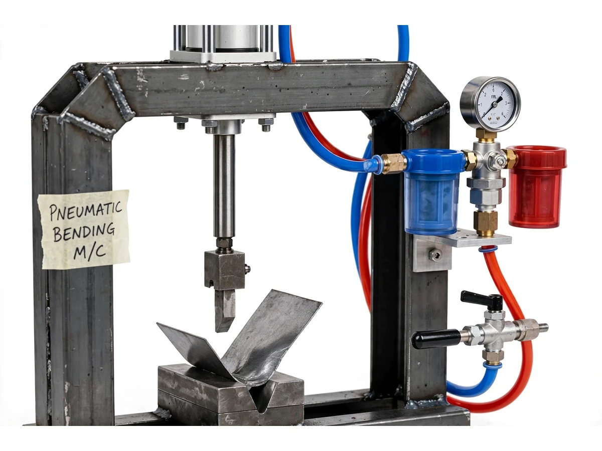
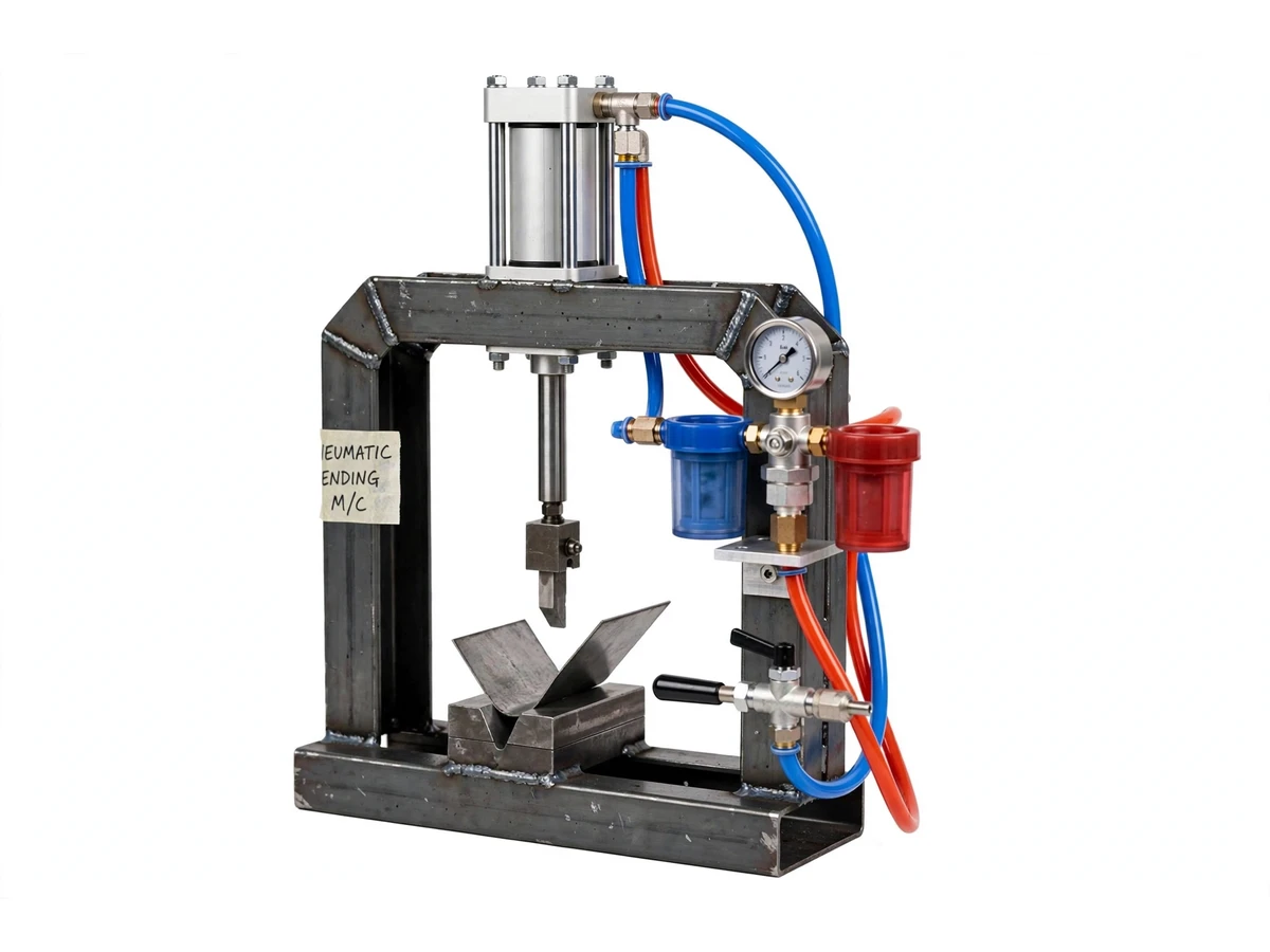
Small workshops and college fabrication labs bend sheet metal with hammers, bench vices or hand brakes — slow, inconsistent, and hard on the operator for anything beyond a one-off bracket. This project builds a compact pneumatic press brake: a double-acting pneumatic cylinder mounted on a welded C-frame drives a punch into a V-die, folding sheet strips (aluminium or mild steel) to a repeatable angle. A 5/2 hand-lever valve gives the operator direct push–pull control, an FRL unit (filter–regulator–lubricator) keeps the air clean and the pressure set, and adjustable stops and a back gauge position each bend. The student fabricates the frame, sizes the cylinder from the required bending force, plumbs the pneumatic circuit, and demonstrates repeat bends on real sheet — a complete, demonstrable manufacturing machine built from standard industrial components.
How it works
- Set the working pressure on the FRL regulator (design target: 6 bar shop air) and confirm the gauge reading.
- Place the sheet strip on the V-die against the back gauge, positioning the bend line under the punch.
- Shift the 5/2 hand-lever valve to extend — the cylinder drives the punch down into the V-die, folding the sheet.
- The punch stops on the adjustable angle stop; hold briefly, then shift the valve to retract the cylinder.
- Remove the bent strip, check the angle with a protractor, and adjust the stop if a different angle is needed.
- Repeat the cycle on successive strips to demonstrate consistent bend angle and flange length across the batch.
- Compute the theoretical bending force from cylinder bore × line pressure and compare with the sheet's bend requirement from standard bending-force data.
Tech stack:
- Double-acting pneumatic cylinder
- 5/2 hand-lever directional control valve
- FRL unit with pressure gauge
- Hardened punch and V-die set
- Welded MS C-frame
- Adjustable back gauge and angle stops
- PU tubing and push-in fittings
- Shop air compressor (external supply)
| Parameter | Value |
|---|---|
| Cylinder bore | Approximately 50–63 mm (design target) |
| Working pressure | Approximately 6 bar shop air (design target) |
| Theoretical force | Approximately 1.2–1.9 kN at 6 bar (design target, bore-dependent) |
| Sheet capacity | Approximately 0.8–1.5 mm MS, 1–2 mm aluminium (design target) |
| Max bend width | Approximately 300 mm (design target) |
| Die | V-die with hardened punch (included) |
| Frame | Welded MS C-frame, approximately 500 × 400 × 900 mm |
| Air supply | External compressor, 6–8 bar (buyer-arranged) |
Project features
- [Cylinder-driven V-die bending] A double-acting pneumatic cylinder drives a hardened punch into a V-die, producing clean air-bends in sheet strips up to the rated width.
- [5/2 hand-lever control valve] Direct manual control of extend and retract — simple, transparent and standard industrial practice for small presses.
- [FRL unit] Filter, regulator and lubricator condition the shop air and set working pressure, with a gauge showing the set pressure during every bend.
- [Adjustable angle stops] Mechanical stops limit punch travel so bend angle repeats across parts — the student demonstrates consistency across a batch of strips.
- [Back gauge] An adjustable fence positions the sheet for consistent flange length on repeated bends.
- [Force sized from first principles] Cylinder bore is selected from the required bending force (pressure × piston area); the report shows the sizing calculation as a design-target figure.
- [Welded C-frame] A rigid MS C-frame carries the cylinder and die set with the working area open at the front for easy loading.
- [Two-hand safe working] The valve placement and guarding keep hands clear of the die during the stroke.
What is included
- Fabricated machine: C-frame, punch, V-die, back gauge, stops
- Double-acting pneumatic cylinder
- 5/2 hand-lever valve and FRL unit with gauge
- PU tubing, fittings and silencers
- Pneumatic circuit diagram and sizing calculations
- Operating procedure and safety notes
- Project report PDF (pneumatics theory, design, procedure)
- PPT presentation for final review
- Viva Q&A preparation document
Limitations & prerequisites
- The 1.2–1.9 kN force is a theoretical design-target calculation (pressure × piston area); actual delivered force is lower due to seal friction and is not claimed as measured.
- Sheet capacity is a design target — thicker or harder stock (stainless) is outside the machine's range.
- Needs an external compressor delivering 6–8 bar; the compressor itself is not included.
- Bend angle depends on operator stop-setting and springback of the material; the student characterizes springback on their own samples.
- Pneumatic exhaust is noisy without silencers; silencers are fitted but the machine still needs a ventilated workspace.
Frequently Asked Questions
How is the bending force calculated?
Force = line pressure × piston area. With a 63 mm bore at 6 bar the theoretical figure is about 1.87 kN. The report shows this sizing step-by-step and states plainly that seal friction makes the delivered force lower — it is presented as a design target, not a measured claim.
What materials and thicknesses can it bend?
Design targets are 0.8–1.5 mm mild steel and 1–2 mm aluminium strips up to 300 mm wide. The student verifies the practical limit on their own samples during commissioning.
Is a compressor included?
No — the machine needs an external 6–8 bar shop-air supply. Any college workshop compressor works; the FRL unit handles filtration and regulation at the machine.
How does the student demonstrate repeatability?
By bending a batch of identical strips and measuring each angle with a protractor — the angle stops and back gauge are the repeatability mechanism, and the spread across the batch is reported honestly.
What pneumatic theory does the viva cover?
Double-acting cylinder construction, 5/2 valve positions and ports, what each FRL stage does, force/pressure/area relations, air consumption per cycle, and why pneumatics suits this duty but not heavy forming.
Is this project suitable for a final-year project?
Yes — for Mechanical Engineering. It is a complete manufacturing machine: fabrication, pneumatic circuit design, sizing calculations and a demonstrated production run of bent parts. Suitable for B.E./B.Tech final-year projects in Mechanical Engineering.
Components & software requirements
- Double-acting pneumatic cylinder
- 5/2 hand-lever directional control valve
- FRL unit with pressure gauge
- Hardened punch and V-die set
- Welded MS C-frame
- Adjustable back gauge and angle stops
- PU tubing and push-in fittings
- Shop air compressor (external supply)
Delivery information
Built-to-order project. Delivery timeline is shared after order confirmation based on current queue.
Support terms
Complete documentation, setup guide, and viva preparation included. Support for setup and explanation provided.