
More project photos (2)
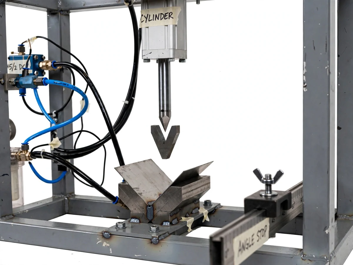
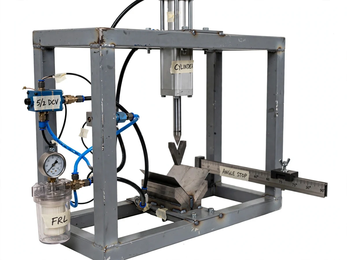
The problem
Small fabrication shops and college workshops bend thin sheet metal by hand on a bench brake — slow, tiring, and inconsistent from part to part, because the operator's feel decides the angle. Hydraulic press brakes solve the force problem but are far too expensive and complex for a teaching lab or a student project budget. Pneumatics sit in the middle: shop air at 6–8 bar is cheap, clean and safe, and a 63 mm bore cylinder produces roughly 2.5 kN of punch force (calculated design target), enough to air-bend 0.5–0.8 mm mild steel sheet up to 150 mm wide. This project is a working bench-top pneumatic bender: welded mild-steel frame, double-acting cylinder, 5/2 DCV solenoid valve for extend/retract, an FRL unit for conditioned air, and a 90° V-die with radiused punch. The adjustable angle stop — a sliding block on a graduated scale bar — is the project's signature: it converts stroke position into a repeatable bend angle, with a calibration procedure that compensates springback per material batch.
Slides the sheet against the angle stop and presses the push-button.
Follow the working sequence
How it works
- Shop air at 6–8 bar enters the FRL unit, which filters out moisture, regulates pressure to the set value (read on the 0–10 bar gauge) and mists lubricating oil into the airline.
- The flat sheet blank is slid against the adjustable angle-stop bar, which locks the blank's edge position so every part starts from the same datum.
- Pressing the push-button energizes the 5/2 DCV solenoid; the valve shifts and routes pressure to the cap end of the double-acting cylinder.
- The cylinder rod drives the radiused V-punch down onto the sheet over the 90° V-die (20 mm opening), air-bending the metal until the punch reaches the preset stop position.
- Releasing the button shifts the valve back; pressure goes to the rod end and the punch retracts, leaving the bend with its natural springback — compensated by the overbend set during calibration.
- The operator checks the included angle with a protractor against the calibration chart, nudges the stop block if needed, and repeats — each cycle takes about 5–8 seconds including loading.
Tech stack:
- Pneumatics: 63 mm bore double-acting cylinder, 5/2 DCV solenoid valve, FRL unit, PU tubing with push-in fittings
- Tooling: 90° V-die (20 mm opening), radiused V-punch, mild-steel tool blocks
- Structure: welded mild-steel square-tube frame, bolted die bed, primer + enamel finish
- Measurement: graduated angle-stop scale (0–150°), 0–10 bar pressure gauge, protractor for calibration
| Parameter | Value |
|---|---|
| Cylinder | 63 mm bore, double-acting, 100 mm stroke (design target) |
| Supply pressure | 6–8 bar shop air (buyer's compressor or lab line) |
| Punch force | ~1.9 kN at 6 bar, ~2.5 kN at 8 bar (calculated design targets) |
| Sheet capacity | 0.5–0.8 mm MS/GI, max width 150 mm (design target) |
| Die | 90° V-die, 20 mm opening, punch nose radius ~2 mm |
| Angle stop | 30–150° included angle, 1° scale resolution |
| Angle repeatability | ±1–2° (expected, after buyer-run calibration) |
| Cycle time | ~5–8 s per bend including loading (expected) |
| Frame | Welded MS square tube, approx 450 × 350 × 600 mm |
| Control | Push-button via 5/2 DCV; optional foot pedal |
Project features
- [Adjustable angle stop] A sliding stop block on a 0–150° graduated scale bar, locked with a wing nut — set the punch stop once for 90°, 120° or custom included angles and every blank bends the same without remarking.
- [Pneumatic drive] A 63 mm double-acting cylinder on 6–8 bar shop air replaces the hand lever — roughly 1.9 kN at 6 bar and 2.5 kN at 8 bar (calculated design targets), so repeat bends are effort-free.
- [5/2 DCV control] One solenoid directional valve handles extend and retract from a single push-button, with quick-exhaust ports fitted for a faster punch return.
- [FRL conditioning] Filter-regulator-lubricator with a 0–10 bar gauge — moisture-free, pressure-regulated, oil-misted air at a dial-set pressure, which is what keeps cylinder seals alive.
- [Interchangeable V-die tooling] A 90° V-die (20 mm opening) and matching radiused V-punch in bolted blocks — the tooling is a separate module, so different die angles can be added later.
- [Fabricated MS frame] Welded square-tube frame with a bolted die bed and painted finish — the cutting, welding, grinding and painting are fully examinable workshop work.
- [Springback calibration procedure] A buyer-run protractor-based procedure with a calibration chart: bend a coupon, measure, record the overbend offset, shift the stop block — repeatable angles from your own data.
- [Viva-ready documentation] Report, PPT and Q&A covering air-bending theory, the force calculation, die-opening selection rules, pneumatic circuit diagrams and safety.
What is included
- Welded mild-steel frame with bolted die bed and painted finish
- 63 mm double-acting pneumatic cylinder with V-punch assembly
- 5/2 DCV solenoid valve, FRL unit with 0–10 bar gauge, PU tubing and fittings
- 90° V-die block (20 mm opening) and adjustable angle-stop bar with graduated scale
- Pneumatic circuit diagram and fabrication drawings
- Springback calibration chart and step-by-step calibration procedure
- Project report PDF (background, theory, force calculation, methodology, results format)
- PPT presentation for final review
- Viva Q&A preparation document (air bending, pneumatics, die design, springback)
Limitations & prerequisites
- Capacity is a design target, not a measured claim — the built unit is sized for 0.5–0.8 mm MS sheet up to 150 mm wide; thicker stock, stainless or wider blanks are out of scope.
- Pneumatic force (~2.5 kN maximum, calculated) cannot match hydraulic press brakes — no heavy-gauge or high-strength-alloy work is claimed.
- Springback varies by material batch; the angle stop must be recalibrated per sheet lot using the included procedure — repeatability is ±1–2° (expected), not CNC-grade.
- The project needs a shop-air source at 6–8 bar; no compressor is supplied with the build.
- Loading is manual — the operator positions each blank by hand, with no automatic feeding or CNC positioning.
Frequently Asked Questions
Why pneumatics instead of hydraulics for this project?
Compressed air at 6–8 bar is cheaper, cleaner and safer for a college lab, and a 63 mm cylinder gives roughly 2.5 kN of punch force (calculated design target) — enough for thin-gauge demonstration bends. Hydraulics needs a power pack, oil handling and bigger safety clearances. The pneumatic circuit is also simpler to draw and defend in the viva.
How does the adjustable angle stop work?
A sliding stop block rides on a graduated scale bar beside the die bed and locks with a wing nut. It limits how far the punch travels, and punch depth maps to bend angle through your calibration chart. Set it once for 90° or 120° bends and every part comes out the same; you recalibrate when the material batch changes.
What is springback and how does the project handle it?
Sheet metal springs back a few degrees after the punch retracts. The kit includes a buyer-run procedure: bend a test coupon, measure the included angle with a protractor, record the overbend offset, and shift the stop block to compensate. The report explains the metallurgy behind springback so you can discuss it confidently.
How is the bending force calculated?
From cylinder physics — force equals pressure times piston area. A 63 mm bore at 8 bar gives roughly 2.5 kN (calculated design target), and the air-bending requirement is estimated with the standard 1.42 × UTS × thickness² × width / die-opening formula. The report shows the full worked calculation, ready for viva questions.
What sheet can it actually bend?
The design target is 0.5–0.8 mm mild steel or GI sheet up to 150 mm wide. Thicker stock, stainless steel or wider blanks exceed the calculated force and are out of scope. Capacity is stated as a design target because nothing is physically built or measured before your order is placed.
Is this project suitable for a final-year project?
Yes — for Mechanical, Production and Mechatronics programs. It combines real fabrication (cutting, welding, finishing), pneumatics (FRL, 5/2 DCV, cylinder sizing), tooling design (V-die geometry, clearances) and a calibration procedure — all hands-on, examinable engineering. Suitable for B.E./B.Tech final-year projects in Mechanical, Production and Mechatronics.
Components & software requirements
- Pneumatics: 63 mm bore double-acting cylinder, 5/2 DCV solenoid valve, FRL unit, PU tubing with push-in fittings
- Tooling: 90° V-die (20 mm opening), radiused V-punch, mild-steel tool blocks
- Structure: welded mild-steel square-tube frame, bolted die bed, primer + enamel finish
- Measurement: graduated angle-stop scale (0–150°), 0–10 bar pressure gauge, protractor for calibration
Delivery information
Built-to-order project. Delivery timeline is shared after order confirmation based on current queue.
Support terms
Complete documentation, setup guide, and viva preparation included. Support for setup and explanation provided.
Download free synopsis (PDF)
Enter your name and email — the synopsis PDF downloads immediately. We may send occasional project updates; no spam, unsubscribe anytime.