
More project photos (2)
The problem
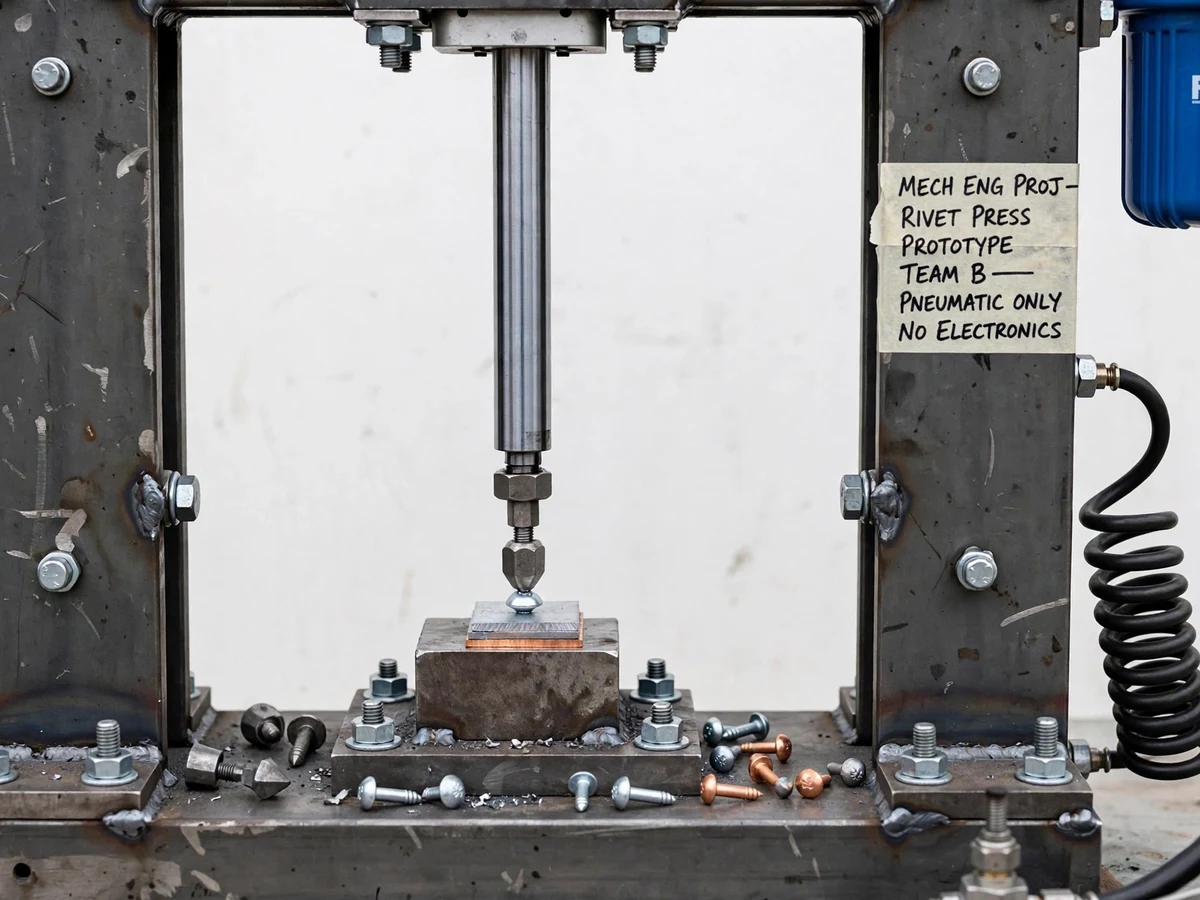
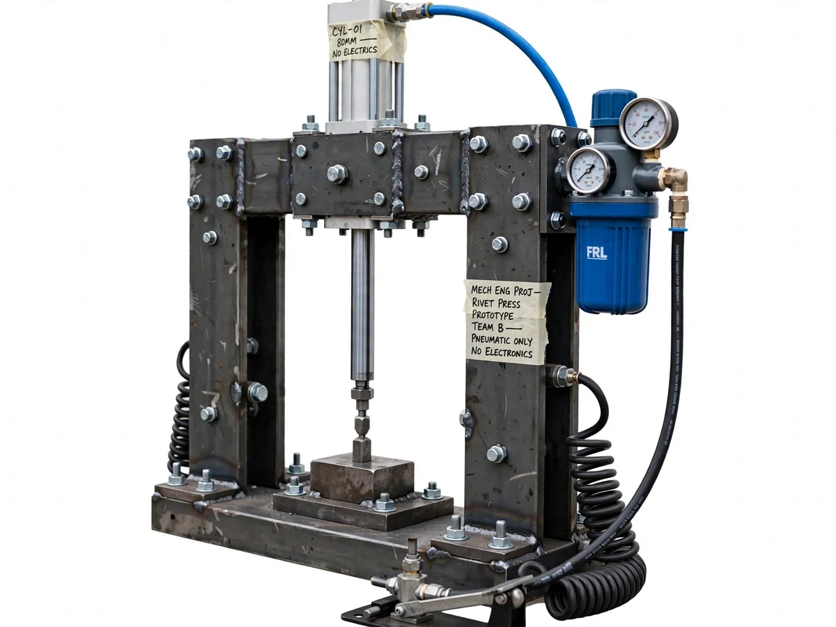
Hand riveting with a hammer is tiring, noisy and hard to repeat: two joints made minutes apart can end up with different head shapes simply because the blows differed. A bench pneumatic press removes that variability by replacing arm effort with a controlled air-driven stroke, while still keeping the joint, the die and the forming action fully visible for study. This project builds such a machine around a steel portal frame, a double-acting pneumatic cylinder mounted above the work zone, and a lower anvil that supports the rivet from below. Pressing a foot pedal sends the upper die down onto the rivet tail; releasing the pedal retracts it. Because the operator's hands stay free to position the sheets, and the working pressure is set on a regulator before the stroke, the same setting can be discussed, recorded and repeated across a set of test joints.
External shop air supply in the approximate 2-8 bar range; not included.
Follow the working sequence
How it works
- Shop air from a compressor (not included) enters the FRL unit, where the filter drains moisture, the regulator knob sets the working pressure in the approximate 2-8 bar range, and the gauge confirms the setting.
- The operator places the overlapping sheets, with a solid rivet already through their aligned holes, onto the lower anvil so the rivet head rests on the anvil face and the tail points up.
- Pressing the foot pedal shifts the 5/2 valve to its extend position, routing regulated air to the cap end of the double-acting cylinder and venting the rod end to exhaust.
- The piston drives the rod and upper die downward; the die meets the rivet tail and, as pressure builds, plastically upsets the tail into a formed head against the sheets.
- Force at the die follows pressure multiplied by piston area — for a 63 mm bore class cylinder the piston area is approximately 3,117 mm², so the design-target force is approximately 0.62 kN at 2 bar and approximately 2.5 kN at 8 bar before friction losses.
- Releasing the pedal lets the valve spring return to its retract position, air is routed to the rod end, and the die lifts clear so the finished joint can be removed and inspected.
- If a joint looks under-formed, the operator raises the regulator setting in small steps and repeats on a fresh rivet; if sheets distort, the setting is lowered — the gauge reading is recorded for each test piece in the report.
Tech stack:
- Double-acting pneumatic cylinder · 63 mm bore class
- 5/2 foot-pedal directional valve
- FRL unit · filter, regulator, lubricator with gauge
- Steel portal frame · welded mild steel
- Interchangeable rivet dies · anvils
- PU air hoses · push-in fittings
- Pneumatic circuit diagram tools
- Compressor supply · approximate 2-8 bar range
| Parameter | Value |
|---|---|
| Cylinder | Double-acting, 63 mm bore class (design target) |
| Cylinder stroke | Approximately 80 mm (design target) |
| Working pressure | Approximate 2-8 bar range, regulator-set (design target) |
| Riveting force | Approximately 0.62-2.5 kN over the pressure range (design-target calculation from pressure x piston area, before friction) |
| Rivet size | Approximate 3-6 mm diameter solid rivets (design target) |
| Sheet stack thickness | Approximately 2-6 mm total stack (design target, material-dependent) |
| Control valve | 5/2 foot-pedal operated, spring return (implemented) |
| Air preparation | FRL unit with pressure gauge (implemented) |
| Frame | Welded mild-steel portal frame (implemented) |
| Air supply | External compressor required, not included (prerequisite) |
| Actuation safety | Foot-pedal only, fixed die guard, prototype-level (stated limitation) |
Project features
- [Foot-pedal 5/2 valve control] A treadle-operated 5/2 directional valve directs air to either side of the cylinder, so one press extends the rod for the riveting stroke and release drives it back up without the operator touching the work zone controls by hand.
- [Adjustable working pressure] The regulator on the FRL unit sets pressure in an approximate 2-8 bar range, and the panel gauge shows the set value before each stroke so force experiments start from a recorded setting, not a guess.
- [Double-acting cylinder drive] Air drives both the downstroke and the return, giving a positive retraction after forming instead of relying on a return spring that would weaken as pressure or friction changes.
- [Interchangeable die and anvil set] Upper dies and lower anvils swap on threaded holders for different rivet head styles, covering solid rivets in an approximate 3-6 mm diameter range within the design envelope.
- [Steel portal frame work zone] The open throat of the welded portal frame lets flat sheets slide in from the front and sit flat on the anvil support, while the frame carries the pressing load back to the cylinder mounting instead of through the workpiece bench.
- [FRL air preparation] A filter-regulator-lubricator unit upstream of the valve removes condensate from the shop line, regulates pressure and adds a light oil mist for the valve and cylinder seals, which is standard practice for pneumatic tools.
- [Prototype-level die guard] A fixed guard plate around the die area discourages fingers entering the pressing zone, and actuation stays foot-only — the guard is a workshop aid for a supervised prototype, not a certified safety device.
What is included
- Working pneumatic riveting machine prototype (portal frame, cylinder, foot-pedal valve, FRL unit, hoses and fittings)
- Interchangeable upper die and lower anvil set for the stated rivet range
- Pneumatic circuit diagram, assembly documentation and component list
- Setup and operating instructions, including pressure-setting and die-change procedure
- Design calculation sheet for piston area and riveting force versus pressure
- Project report PDF (background, riveting theory, design calculations, methodology)
- Project abstract PDF
- PPT presentation for final review
- Viva Q&A preparation document (pneumatic valves, FRL function, force calculation, rivet upset, frame loading)
Limitations & prerequisites
- Force figures are design-target calculations from pressure and piston area, not measured results: seal friction, hose pressure drop and valve flow reduce the force actually delivered at the die.
- Rivet range is a design target for an approximate 3-6 mm diameter in softer rivet materials at the upper pressure settings; hard steel rivets at the top of that size range may need more force than this cylinder can provide.
- Sheet stack is an approximate 2-6 mm design target and depends on material: thin sheets can distort if pressure is set too high, and thick or high-strength stacks may not form a complete head.
- An external compressor with adequate flow is required and is not included; the machine only works while connected to a live air supply in the stated pressure range.
- The die guard and foot-only actuation are prototype-level measures for supervised workshop use only — this is not a certified industrial press and has no interlocked guarding or light curtains.
- Joint quality depends on operator setup: rivet length, hole clearance, die alignment and dwell on the pedal all affect the formed head, so test pieces are needed before judging a setting.
- No cycle-time or production-rate claim is made: this is a manually loaded bench prototype for learning and demonstration, not a production riveting line.
Frequently Asked Questions
Is this project suitable for a final-year project?
Yes, for Mechanical Engineering programmes. It brings together pneumatic circuit design, a 5/2 valve and double-acting cylinder, a force calculation from first principles, frame design under a pressing load, and experimental comparison of formed heads at different pressure settings, which together give concrete material for the report and viva.
How is the riveting force controlled?
By air pressure. The regulator on the FRL unit sets the pressure supplied to the cylinder, and force at the piston is that pressure multiplied by the piston area, minus friction losses. Turning the regulator up within the approximate 2-8 bar range raises the available force; the gauge shows the setting so each test joint can be linked to a recorded pressure.
Why use a foot pedal instead of a hand lever or a push button?
The pedal leaves both hands free to hold and position the sheets on the anvil, and it keeps the operator's hands away from the die while the stroke happens. A 5/2 treadle valve also makes the extend and retract actions a single, easy-to-explain pneumatic circuit with no electrical control at all.
What rivets and sheets can it handle?
The design target is solid rivets of approximately 3-6 mm diameter through a total sheet stack of approximately 2-6 mm, with interchangeable dies for the head style. Those figures are targets that depend on rivet and sheet material, not measured guarantees, and the limitations section explains where the envelope runs out.
What air supply does the machine need?
A workshop compressor that can hold the set pressure in the approximate 2-8 bar range while the cylinder cycles. The compressor is not included. Air passes through the FRL unit first, so a supply with heavy moisture or dirt will shorten seal life even though the filter helps.
Can the machine be customised?
Realistic changes include a different cylinder bore or stroke, extra die profiles for other head styles, a larger throat frame for wider sheets, and flow-control valves to slow the approach speed. Each change affects the force calculation and frame loading, so it is discussed against the design targets before being added.
Components & software requirements
- Double-acting pneumatic cylinder · 63 mm bore class
- 5/2 foot-pedal directional valve
- FRL unit · filter, regulator, lubricator with gauge
- Steel portal frame · welded mild steel
- Interchangeable rivet dies · anvils
- PU air hoses · push-in fittings
- Pneumatic circuit diagram tools
- Compressor supply · approximate 2-8 bar range
Delivery information
Built-to-order project. Delivery timeline is shared after order confirmation based on current queue.
Support terms
Complete documentation, setup guide, and viva preparation included. Support for setup and explanation provided.
Download free synopsis (PDF)
Enter your name and email — the synopsis PDF downloads immediately. We may send occasional project updates; no spam, unsubscribe anytime.