
More project photos (2)
The problem
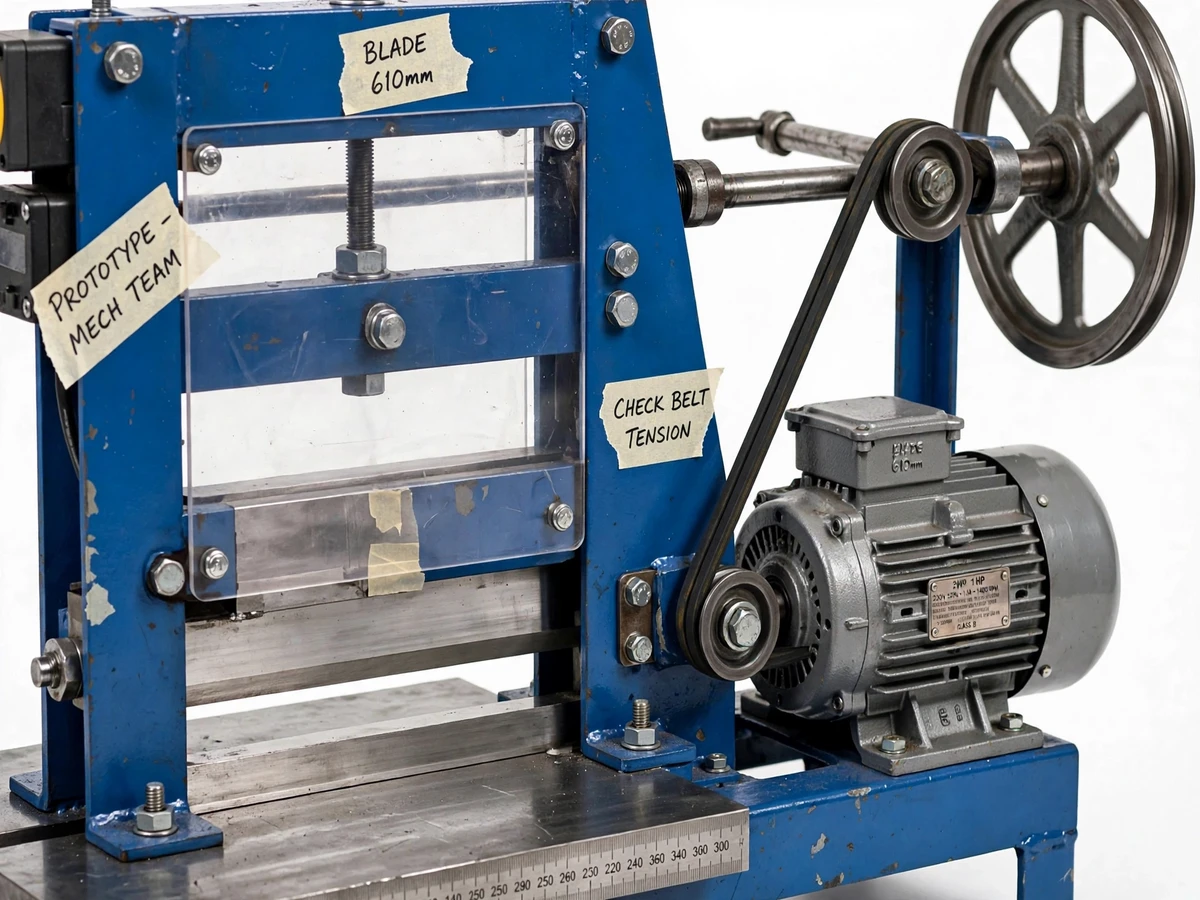
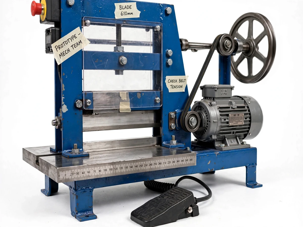
Cutting sheet metal by hand in a college workshop means a hand lever shear, slow repeat strokes and inconsistent edges — fine for one piece, miserable for a batch of sheet-metal models, enclosures or fabricated brackets. Commercial motorized shearing machines exist, but they are expensive, oversized for a student project and offer no insight into how shearing force, blade clearance and rake angle are actually set up. This project bridges that gap: a compact motorized guillotine-type shearing machine, built from an MS angle-iron frame, driven by a standard 1 HP single-phase motor through a belt-pulley reduction and a crank-flywheel linkage. It is designed to cut mild-steel sheet up to about 2 mm thick over a 610 mm blade, actuated by a single footswitch press so both hands stay free to guide the work. Because the student sizes the motor, works out the linkage geometry and sets the blade gap themselves, the machine is a genuine mechanical-design project — not an assembled kit.
Sets the blade gap, positions the sheet and presses the footswitch.
Follow the working sequence
How it works
- The operator sets the blade gap for the sheet thickness using the shim and adjustment-screw arrangement on the blade mounts, then checks alignment along the 610 mm blade.
- The sheet is laid on the support table and slid against the measuring scale to the required cut line, keeping hands clear of the blade zone.
- Pressing the footswitch energizes the motor circuit; the 1 HP motor spins the pulley train, and the flywheel carries the crank through one cutting stroke.
- The crank drives the upper blade down through the sheet in a single guillotine pass, shearing it against the fixed lower blade.
- A limit switch at the bottom of the stroke cuts the drive, and the blade returns to the raised rest position; releasing and re-pressing the pedal starts the next cut.
- The polycarbonate blade guard blocks finger access to the blade edges during the stroke, and the emergency-stop button halts the motor instantly if anything looks wrong.
- After cutting, the operator inspects the edge quality and notes any burr or warp, adjusting blade gap or feed alignment before the next piece.
Tech stack:
- 1 HP single-phase induction motor (1440 rpm, typical)
- V-belt and stepped pulley reduction drive
- Crank · flywheel · connecting-rod linkage
- High-carbon steel shear blades (upper + lower)
- MS angle and plate welded C-frame
- Industrial footswitch pedal with limit-switch cutoff
- Polycarbonate blade guard · emergency-stop pushbutton
- Engraved measuring scale on steel support table
| Parameter | Value |
|---|---|
| Cutting capacity | Approximately 2 mm max thickness (design target, mild-steel sheet) |
| Blade length | Approximately 610 mm (24 in, design target) |
| Motor | 1 HP (approximately 0.75 kW) single-phase induction, 1440 rpm (typical) |
| Drive | V-belt + pulley reduction with flywheel energy storage |
| Actuation | Footswitch pedal, one stroke per press |
| Blade adjustment | Shim + screw adjustable blade gap (clearance) |
| Blade guard | Polycarbonate guard over the blade zone |
| Safety cutoff | Limit switch at stroke end; red emergency-stop button |
| Frame | Welded mild-steel C-frame, fabrication-shop grade |
| Table | Steel support table with engraved measuring scale |
Project features
- [Footswitch actuation] A heavy-duty floor pedal triggers one full cutting stroke; a limit switch ends the stroke and returns the blade, so the operator's hands stay on the workpiece at all times.
- [Adjustable blade gap] Upper and lower shear blades mount on shim and screw adjustments, letting the blade clearance be set to suit sheet thickness — the exact setup a real shear operator performs.
- [1 HP motor + belt-pulley drive] A standard 1 HP single-phase induction motor drives the crank through a V-belt reduction, giving the flywheel time to store energy before each cut and smoothing the load on the motor.
- [Guillotine blade mechanism] A crank-flywheel linkage converts rotation into the straight-line cutting stroke of the 610 mm blade, the same mechanism family used in commercial guillotine shears.
- [Measuring-scale support table] A flat steel table with an engraved measuring scale lets the operator position and align each cut repeatably without separate measuring tools.
- [Blade guard and emergency stop] A polycarbonate guard covers the blade zone and a red emergency-stop button cuts motor power instantly; safe handling procedure is documented in the manual.
- [Welded MS C-frame] A rigid C-frame fabricated from mild-steel angles and plates absorbs the shearing force without visible flex at the rated capacity.
- [Limit-switch stroke cutoff] A limit switch at the end of the stroke stops the cycle automatically, preventing over-travel and double strokes from a stuck pedal.
What is included
- Complete motorized shearing machine: frame, motor, belt-pulley drive, crank-flywheel linkage, upper and lower blades, footswitch, limit switch, blade guard, emergency stop, support table with scale
- Fabrication drawings and bill of materials with standard part references
- Blade-gap setup and calibration procedure (shim adjustment method)
- Electrical wiring diagram for the motor, footswitch and limit-switch circuit
- Safe operation manual with emergency procedures
- Project report PDF (design calculations, methodology, results)
- PPT presentation for final review
- Viva Q&A preparation document (shearing theory, linkage design, safety systems)
Limitations & prerequisites
- The ~2 mm cut capacity is an approximate design target and is material-dependent — harder alloys, stainless or thicker sheet will not cut cleanly and must not be attempted on the prototype.
- Blade edge life depends on usage and maintenance; the blades need periodic sharpening and gap re-setting, which is documented as a maintenance procedure, not a defect.
- This is a student prototype with no industrial safety certification — the guard and emergency stop are included, but proper operator training and supervision are required for every use.
- Frame tolerances are fabrication-shop grade, not machined precision; cut edges may show slight burr or camber that a commercial shear would not.
- Noise and vibration are higher than a commercial machine — the belt drive and single-cylinder linkage pulse are inherent to this drive layout.
- Cutting is single-stroke guillotine only — no continuous roll cutting, no notching and no angle cutting attachments.
Frequently Asked Questions
How does the footswitch control work?
Pressing the floor pedal energizes the motor circuit and the crank linkage executes one full cutting stroke; a limit switch at the bottom of the stroke ends the cycle and returns the blade. Hands stay on the workpiece the whole time, which is the safety point of the design.
How is the blade gap adjusted?
The upper and lower blades sit on shim-and-screw mounts. Adding or removing shims and turning the adjustment screws changes the clearance between the blades so it matches the sheet thickness — the same setup procedure used on industrial guillotine shears, and the viva topic examiners ask about first.
What thickness can it actually cut?
The design target is mild-steel sheet up to about 2 mm thick. Capacity is approximate and material-dependent — harder or thicker stock is explicitly out of scope and must not be fed into the machine.
Is a guard really necessary on a student machine?
Yes. The polycarbonate blade guard covers the blade zone during the stroke, and the emergency stop cuts motor power instantly. The operation manual also documents the required safe-handling procedure and supervision.
Why a crank-flywheel linkage instead of direct motor drive?
The flywheel stores rotational energy between strokes and releases it during the cut, so a small 1 HP motor can deliver the high instantaneous shearing force — this energy-storage reasoning is a strong viva talking point.
Is this project suitable for a final-year project?
Yes — for Mechanical, Production and Mechatronics programs. It covers mechanism design, motor selection, fabrication, safety systems and a working prototype the student can demonstrate live. Suitable for B.E./B.Tech final-year projects in Mechanical and Production Engineering.
Components & software requirements
- 1 HP single-phase induction motor (1440 rpm, typical)
- V-belt and stepped pulley reduction drive
- Crank · flywheel · connecting-rod linkage
- High-carbon steel shear blades (upper + lower)
- MS angle and plate welded C-frame
- Industrial footswitch pedal with limit-switch cutoff
- Polycarbonate blade guard · emergency-stop pushbutton
- Engraved measuring scale on steel support table
Delivery information
Built-to-order project. Delivery timeline is shared after order confirmation based on current queue.
Support terms
Complete documentation, setup guide, and viva preparation included. Support for setup and explanation provided.
Download free synopsis (PDF)
Enter your name and email — the synopsis PDF downloads immediately. We may send occasional project updates; no spam, unsubscribe anytime.