
More project photos (2)
The problem
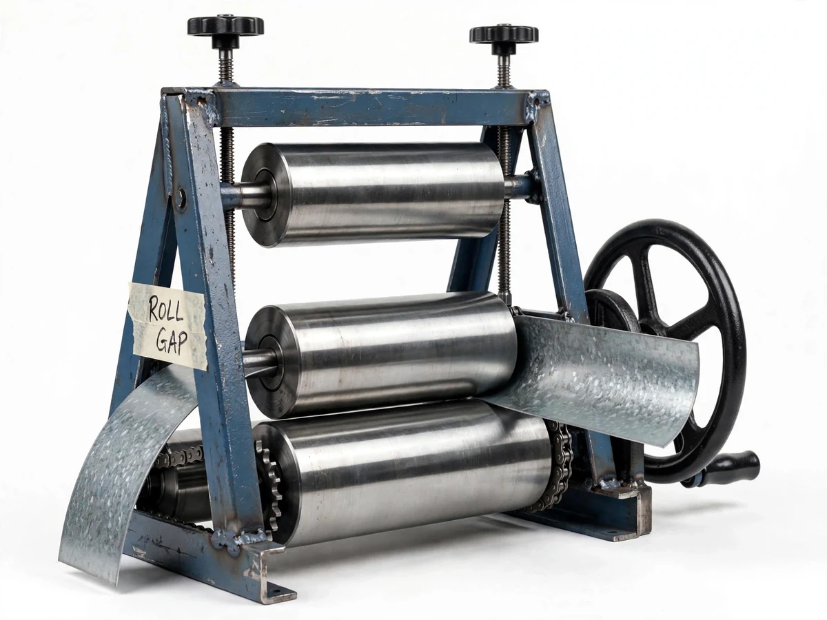
Small fabrication shops, college workshops and diploma labs constantly need to bend sheet metal into cylinders, arcs and ducts — for tanks, guards, machine covers and pipe sections — but power-operated rolling machines are expensive, bulky and need a 3-phase supply that most teaching labs do not have. Students study bending theory (neutral axis, bend allowance, springback) in manufacturing courses yet rarely build the machine that performs the bend. This project closes that gap with a manually operated 3-roller pyramid-type rolling machine fabricated from standard mild-steel sections: three solid steel rollers, a top roller that moves vertically through twin lead screws to set the roll gap, and a hand crank driving both bottom rollers through a chain drive. Designed for mild-steel sheet up to about 2 mm thick and 600 mm wide (design targets), it rolls cylinders and arcs, and with the top roller tilted it can form cones. Because there is no motor and no power supply, it runs in any lab, and every part of it — cutting, machining, welding, fitting, alignment — is built and verified by the student.
Sets the gap, feeds the sheet and turns the crank pass by pass.
Follow the working sequence
How it works
- The operator sets the initial roll gap: both lead-screw handwheels turn together to lower the top roller until the gap matches the sheet thickness plus a small pinch for the first pass.
- The sheet edge is fed between the top and bottom rollers and the top roller is pinched down to grip it firmly without slipping.
- The operator turns the hand crank; the roller-chain drive rotates both bottom rollers at the same speed, drawing the sheet through the roll nip.
- The offset top roller imposes curvature on the sheet; after each pass the top roller is lowered slightly (typically a fraction of a turn of the handwheels) and the pass is repeated to tighten the radius progressively.
- For cones, one lead screw is set lower than the other so the top roller tilts, producing a tapered bend; for cylinders both screws stay equal.
- Once the target radius is reached, the top roller is raised clear and the formed cylinder is slid off the roll end; the seam is then closed by welding or riveting.
Tech stack:
- Mild steel fabrication (angle, channel, plate)
- EN8 steel · lathe-turned rollers
- Arc welding · grinding and finishing
- Roller-chain drive (1:1 both bottom rolls)
- Lead-screw gap adjustment with handwheels
- Pillow-block / bush bearings
- Sheet-metal bending theory (bend allowance, springback)
- CAD fabrication drawings (frame, rollers, assembly)
| Parameter | Value |
|---|---|
| Rollers | 3 × solid steel, approximately 60 mm diameter × 650 mm long (design target) |
| Roll gap | Adjustable 0–10 mm via twin lead screws (design target) |
| Sheet thickness | Up to approximately 2 mm mild steel (design target); approximately 1 mm stainless (expected) |
| Working width | Approximately 600 mm (design) |
| Frame | MS angle 50 × 50 × 5 mm, arc-welded and braced (design) |
| Drive | Hand crank + roller chain, 1:1 to both bottom rollers (design) |
| Adjustment screws | Twin lead screws, approximately M20 × 2.5 pitch with handwheels (design target) |
| Minimum bend radius | Approximately 75 mm on 1 mm MS sheet (design target, buyer-verified) |
| Overall size | Approximately 900 × 500 × 800 mm (approximate) |
| Weight | Approximately 70–90 kg (approximate) |
Project features
- [Three-roller pyramid layout] Two fixed bottom rollers and one vertically adjustable top roller in the classic pyramid arrangement — the geometry that turns flat sheet into cylinders and arcs with a simple manual pass.
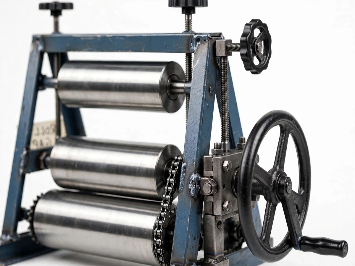
- [Adjustable roll gap with twin lead screws] The top roller rides in sliding bearing blocks moved by two lead screws with handwheels, so the gap is set precisely for each sheet thickness and tightened pass by pass to control the bend radius.
- [Manual hand-crank chain drive] A hand crank on the drive shaft powers both bottom rollers through a roller-chain drive at the same speed — no electricity, no motor, safe to demonstrate in any lab.
- [Lathe-turned steel rollers] Solid steel rollers machined on a lathe for a smooth, parallel working surface — the build's critical machining step, fully documented with tolerances in the fabrication guide.
- [Welded mild-steel frame] A rigid frame from standard MS angle and channel, arc-welded and cross-braced; the guide covers joint preparation, welding sequence and squareness checks.
- [Cone rolling by top-roll tilt] Each lead screw adjusts independently, so the top roller can be set at a slight tilt to roll tapered cones as well as straight cylinders.
- [Quick sheet release] The top roller lifts clear on its screws so the formed cylinder slides off the roll end without forcing or deforming the part.
What is included
- Fabricated and assembled 3-roller rolling machine (the physical build)
- Fabrication drawings: frame, rollers, bearing blocks and full assembly (CAD + PDF)
- Bill of materials with standard section sizes and sourcing notes
- Step-by-step fabrication guide: cutting, lathe work, welding sequence, fitting and alignment checks
- Bending procedure sheet: gap setting, pass schedule, cone setup and sheet release
- Project report PDF (bending theory, design calculations, fabrication log, commissioning checks)
- PPT presentation for the final review
- Viva Q&A preparation document (roll bending, springback, weld quality, alignment)
Limitations & prerequisites
- Manual drive means rolling speed and pass consistency depend on the operator; it is a teaching and small-job machine, not a production bender.
- The 2 mm MS / 600 mm capacity figures are design targets — the real limit is established on the buyer's own build during commissioning, never claimed as measured here.
- Minimum bend radius is thickness-dependent and approximate; tight radii on thicker sheet can mark the surface or deflect the rollers.
- Sheet ends stay flat through the first and last part of each pass (no powered pre-bend), so leading/trailing flats must be trimmed or accepted.
- At roughly 70–90 kg it needs a fixed floor or bench position and two people to move safely.
- Part quality depends directly on roller parallelism and frame squareness — the guide includes the alignment checks the buyer must perform and record.
Frequently Asked Questions
How does the adjustable roll gap work?
The top roller sits in sliding bearing blocks, one at each end, and each block is raised or lowered by its own lead screw with a handwheel. Turning both handwheels together moves the roller straight up or down to set the gap for the sheet thickness; lowering it a little between passes tightens the bend radius progressively.
What thickness of sheet can it roll?
The design target is mild-steel sheet up to about 2 mm thick and 600 mm wide, and about 1 mm stainless steel. These are design targets verified on the buyer's own build during commissioning — the report documents the actual capacity achieved, not a pre-claimed number.
Can it roll cones as well as cylinders?
Yes. Because each end of the top roller adjusts independently, setting one lead screw lower than the other tilts the roller and produces a tapered bend — a cone. Equal settings on both screws give straight cylinders and arcs.
Does it need any power supply?
No. Both bottom rollers are driven by a hand crank through a roller-chain drive, and the gap is set with handwheels. It runs in any lab or workshop with no electricity, which also makes it safe to demonstrate during the viva.
What fabrication skills does the build teach?
Reading fabrication drawings, cutting and preparing MS sections, arc welding with a documented sequence, lathe-turning the rollers to parallel finish, fitting bearings and chain drive, and the alignment checks (roller parallelism, frame squareness) that decide part quality.
Is this project suitable for a final-year project?
Yes — for Mechanical and production/manufacturing programs. It combines bending theory and design calculation with genuine hands-on fabrication (machining, welding, fitting), and the finished machine demonstrates live during the viva. Suitable for B.E./B.Tech final-year projects in Mechanical.
Components & software requirements
- Mild steel fabrication (angle, channel, plate)
- EN8 steel · lathe-turned rollers
- Arc welding · grinding and finishing
- Roller-chain drive (1:1 both bottom rolls)
- Lead-screw gap adjustment with handwheels
- Pillow-block / bush bearings
- Sheet-metal bending theory (bend allowance, springback)
- CAD fabrication drawings (frame, rollers, assembly)
Delivery information
Built-to-order project. Delivery timeline is shared after order confirmation based on current queue.
Support terms
Complete documentation, setup guide, and viva preparation included. Support for setup and explanation provided.
Download free synopsis (PDF)
Enter your name and email — the synopsis PDF downloads immediately. We may send occasional project updates; no spam, unsubscribe anytime.