
More project photos (2)
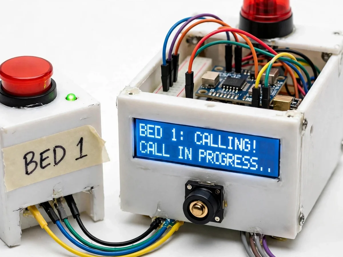
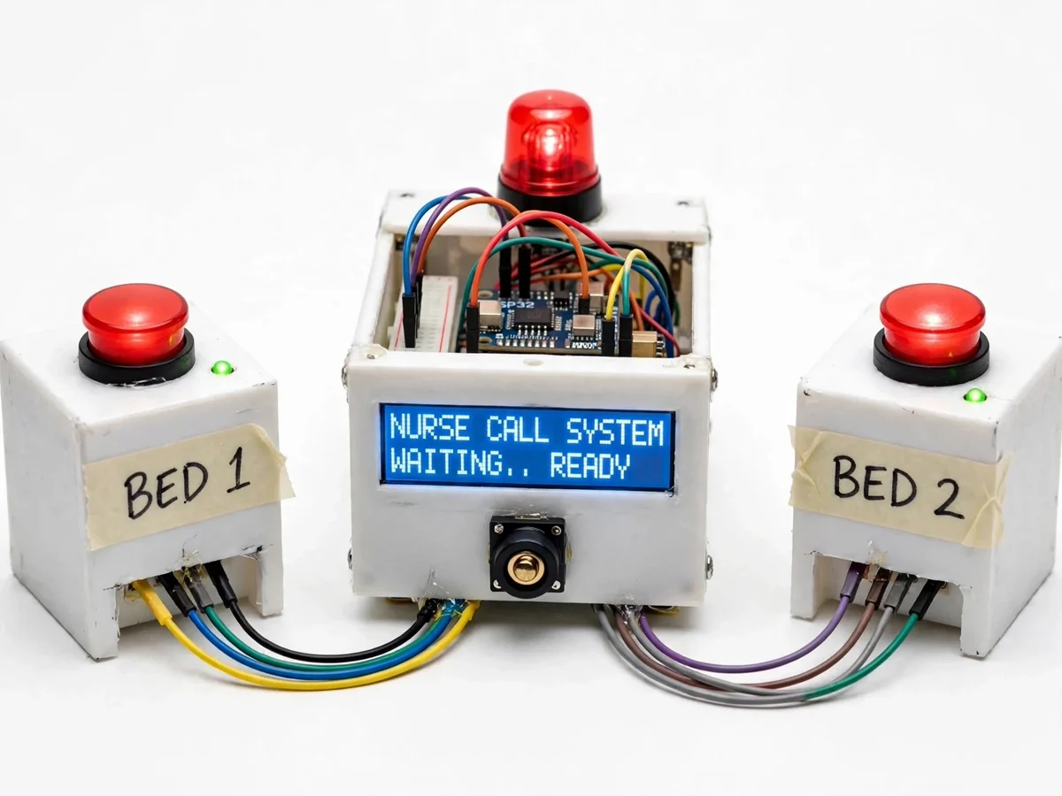
The problem
In hospital wards, patients need a fast, reliable way to reach nurses, and nurses need to know exactly which bed is calling. Wired call-bell systems are expensive to retrofit into old buildings and give no record of how long a call waited — yet delayed response to a patient call is a genuine patient-safety concern. A wireless IoT call system solves both problems: every bed gets a simple button, the central console identifies the calling bed instantly, and call-to-response times are logged for shift review. This project builds that system at demonstration scale with ESP32 nodes — wireless alerting, central monitoring, acknowledgement workflow and logging — in a form students can extend toward real ward requirements.
How it works
- The patient presses the bedside call button; the ESP32 wakes and transmits its configured bed ID.
- The message travels over Wi-Fi to the central unit (MQTT on the local network, or ESP-NOW link).
- The console LCD adds the bed to the active-call queue and the buzzer sounds.
- The nurse presses acknowledge on the console; the bedside lamp switches to the "nurse on the way" state.
- Both timestamps are written to the response log, viewable on the dashboard.
- Pressing cancel at the bedside clears the call; unacknowledged calls re-alert after the escalation timeout.
Tech stack:
- ESP32-WROOM-32 nodes (bedside units + central console)
- Wi-Fi with MQTT (local broker) or ESP-NOW link
- 16×2 LCD with I2C backpack on console
- Buzzer and beacon lamp for alerts
- Single-file HTML/CSS/JS dashboard served by central ESP32
- Arduino IDE firmware
- USB 5 V power; battery option for bedside units
| Parameter | Value |
|---|---|
| Nodes | Central console + 2–4 bedside units typical (configurable) |
| Link | Wi-Fi (local) or ESP-NOW; design target latency under 2 s |
| Range | Indoor Wi-Fi dependent, approx 10–30 m typical |
| Console display | 16×2 LCD with active-call queue |
| Alerts | Buzzer + beacon lamp; escalation re-alert configurable |
| Dashboard | Local web page; no internet or cloud needed |
| Power | USB 5 V; bedside units support battery option |
| Logging | Per-bed call/acknowledge timestamps |
| Status | Academic prototype — not certified medical equipment |
Project features
- [Wireless bedside call units] Battery/USB-powered ESP32 button units — one per bed — with a large illuminated call button and a cancel button.
- [Bed-number identification] Each unit carries a configured bed ID, so the console and dashboard show exactly which bed is calling.
- [Nurse-station console] Central ESP32 receiver with 16×2 LCD listing active calls in order, plus a buzzer and beacon lamp.
- [Acknowledgement workflow] The nurse acknowledges a call at the console (or from the dashboard); the bedside unit's lamp changes state to confirm.
- [Response-time logging] Call-raised and acknowledged timestamps are logged per bed for shift-level review.
- [Local Wi-Fi dashboard] A single-page web dashboard on the central unit shows live bed status without any cloud account.
- [Escalation timer] Calls unacknowledged beyond a configurable time re-alert with a distinct tone (configurable).
What is included
- Central nurse-station console (ESP32, LCD, buzzer, beacon)
- 2–4 wireless bedside call button units
- Complete firmware (nodes + console + dashboard)
- Circuit and wiring documentation
- Project report PDF (architecture, protocol, testing procedure, limitations)
- PPT presentation for final review
- Viva Q&A preparation document (ESP32, MQTT/ESP-NOW, IoT alerting)
- Setup and demonstration guide
Limitations & prerequisites
- Academic prototype only — not certified medical equipment and not for life-critical or emergency use; the disclaimer ships in the report and must stay in any presentation of the work.
- Alert delivery depends on the local Wi-Fi environment; dead zones and router outages affect it.
- Battery-powered bedside units need regular charging; the dashboard shows a low-battery flag but cannot prevent a flat battery.
- Response-time logs are only as disciplined as the acknowledgement workflow — skipped acknowledgements skew the data.
- No encryption beyond standard Wi-Fi security; patient-data handling is the deployer's responsibility.
Frequently Asked Questions
Which controller is used?
ESP32-WROOM-32 on every node and the central console, programmed in the Arduino IDE. Bedside units can use ESP32-C3 variants as a customization.
Does it need the internet?
No. The console, dashboard and logging all run on the local Wi-Fi network. Optional cloud push or SMS alerts can be added as customization.
How many beds can it cover?
The base build ships with 2–4 bedside units; more can be added since each unit just needs a unique bed ID — range and router capacity are the practical limits.
Can it be used in a real hospital?
No — it is an academic prototype demonstrating IoT alerting. Real deployment needs certified medical-device engineering, redundancy and compliance work far beyond this project.
What are the main limitations?
Wi-Fi dependence, battery charging discipline, prototype-grade (non-certified) status, and logs that depend on staff acknowledgement discipline.
Is this project suitable for a final-year project?
Yes — for IoT, Embedded Systems, Electronics and Computer programs. It demonstrates wireless sensor nodes, MQTT/ESP-NOW messaging, central monitoring and dashboard design. Suitable for B.E./B.Tech final-year projects in IoT, Embedded Systems and Electronics.
Components & software requirements
- ESP32-WROOM-32 nodes (bedside units + central console)
- Wi-Fi with MQTT (local broker) or ESP-NOW link
- 16×2 LCD with I2C backpack on console
- Buzzer and beacon lamp for alerts
- Single-file HTML/CSS/JS dashboard served by central ESP32
- Arduino IDE firmware
- USB 5 V power; battery option for bedside units
Delivery information
Built-to-order project. Delivery timeline is shared after order confirmation based on current queue.
Support terms
Complete documentation, setup guide, and viva preparation included. Support for setup and explanation provided.