
More project photos (3)

The problem
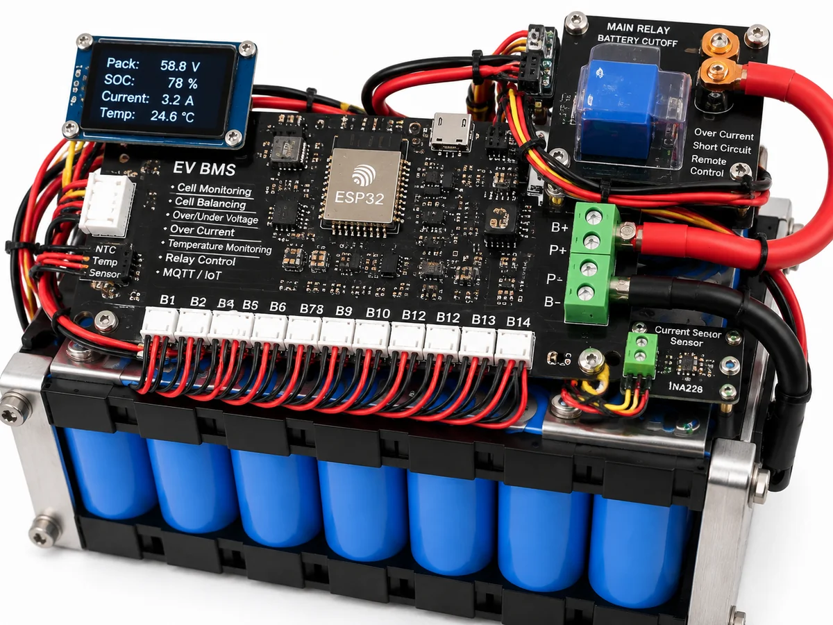
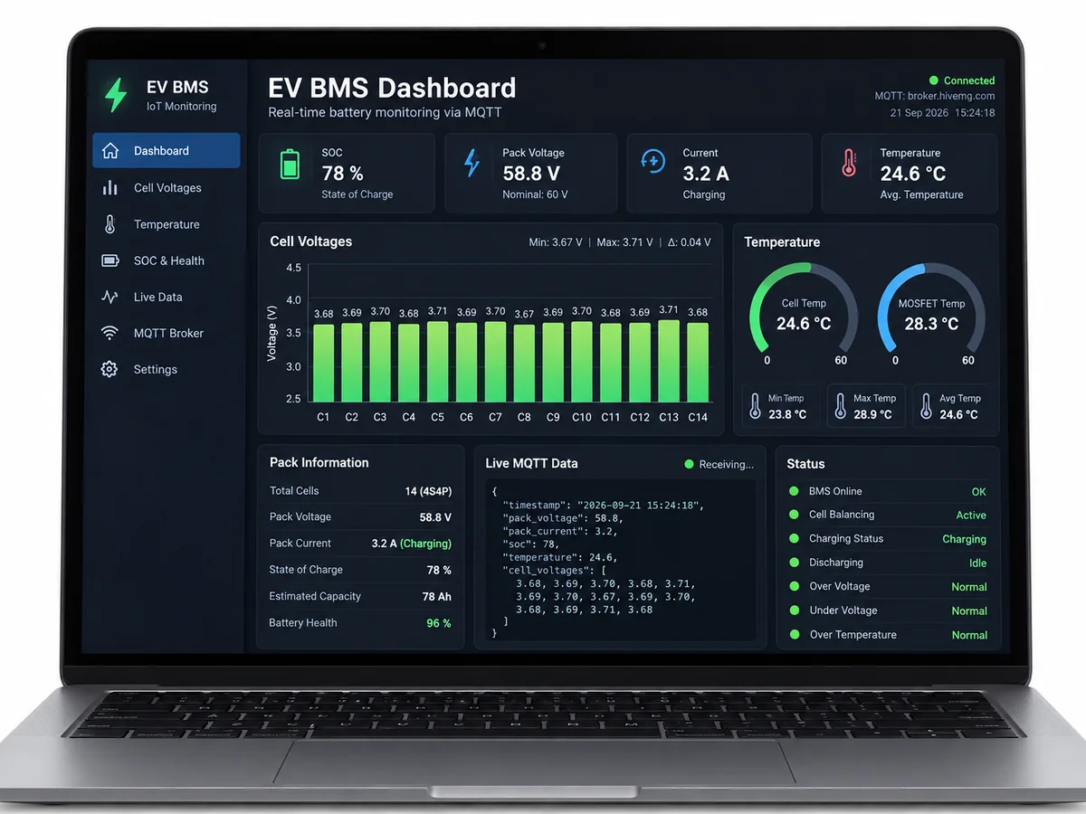
Batteries are the heart of every electric vehicle — and the number one safety concern. This IoT-Based Battery Management System (BMS) is a working EV battery prototype built around the ESP32: it continuously monitors every cell's voltage, watches pack temperature, estimates state-of-charge (SOC), and streams everything over MQTT to a live dashboard. When anything crosses a safety limit — over-voltage, under-voltage, or over-temperature — a relay instantly cuts off the load/charger. It is the complete final-year story in one box: embedded sensing, power safety, wireless telemetry, and a dashboard you can demo live. Whether your guide asks about cell monitoring, SOC estimation, or IoT protocols, this project has an answer ready — and the report, PPT, and viva Q&A we include make sure you're prepared for every one of them.
Voltage sensor modules sample each cell of the lithium pack through the ESP32 ADC.
Follow the working sequence
How it works
- Voltage sensor modules sample each cell of the lithium pack; the ESP32 reads them through its ADC.
- NTC thermistors mounted on the pack feed temperature readings to the ESP32.
- Firmware estimates the state-of-charge (SOC) and checks every reading against safety thresholds.
- Telemetry is published as JSON over MQTT every few seconds to the dashboard.
- The dashboard renders live cell voltage bars, temperature gauges, and the SOC ring.
- If any cell goes over-voltage/under-voltage or the pack overheats, the relay disconnects the load or charger immediately and raises an on-device + dashboard alert.
- Once readings return to the safe band, the system can re-enable the circuit — every event is logged for your report.
Project features
- Per-cell voltage monitoring of a multi-cell lithium battery pack
- Pack temperature tracking with NTC thermistors
- State-of-charge (SOC) estimation from voltage + discharge behavior
- MQTT telemetry — live battery data published to a cloud/local dashboard
- Automatic safety cutoff via relay on over-voltage, under-voltage, and over-temperature
- Live dashboard with cell voltage bars, temperature gauges, and SOC percentage
- On-board status display for quick readings without the dashboard
- Configurable safety thresholds in firmware — easy to tune and explain in viva
- Event logging of cutoff incidents and charge/discharge cycles
- Low-cost, student-friendly components with full wiring documentation
What is included
- Fully assembled and tested BMS prototype (built to order)
- Complete ESP32 firmware source code with comments
- Wiring/circuit diagram of the full setup
- Project report PDF (synopsis, design, implementation, testing, results)
- PPT presentation for your final demo
- Viva Q&A sheet covering BMS concepts, SOC, MQTT, and safety logic
Advantages
- Per-cell voltage monitoring of a multi-cell lithium battery pack plus pack temperature tracking with NTC thermistors.
- State-of-charge (SOC) estimation from voltage and discharge behaviour.
- MQTT telemetry — live battery data published to a cloud/local dashboard.
- Automatic safety cutoff via relay on over-voltage, under-voltage, and over-temperature, with event logging of cutoff incidents and charge/discharge cycles.
- Live dashboard with cell voltage bars, temperature gauges, and SOC percentage; on-board status display for quick readings; configurable safety thresholds in firmware.
Disadvantages
- Prototype-scale demonstration unit — not automotive-grade and not intended for road-going EVs.
- SOC estimation is approximate (voltage-based with discharge modelling; no precision current shunt in the base build).
- Maximum switched current is limited by the relay rating — sized for the demo pack.
- Telemetry needs WiFi connectivity with no cellular backup; cell balancing is indicative, not full active balancing.
Limitations & prerequisites
- A prototype-scale demonstration unit — not automotive-grade and not intended for road-going EVs
- SOC estimation is approximate (voltage-based with discharge modeling; no precision current shunt in the base build)
- Maximum switched current is limited by the relay rating — sized for the demo pack
- Telemetry needs WiFi connectivity; no cellular backup in the base version
- Cell balancing is indicative (imbalance flagged on dashboard), not full active balancing
Components & software requirements
- ESP32 development board (WiFi-enabled controller)
- Lithium battery pack (demo-scale, e.g., 3S 18650 configuration)
- Voltage sensor modules (per-cell sensing)
- NTC thermistors (pack temperature)
- Relay module (safety cutoff for load/charger)
- Status display (OLED/LCD)
- MQTT broker (local or cloud) + live dashboard
- Jumper wires, connectors, and mounting hardware
Download free synopsis (PDF)
Enter your name and WhatsApp number — the synopsis PDF downloads immediately. We may send occasional project updates on WhatsApp; no spam.