
More project photos (2)

The problem
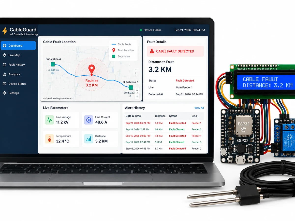
When an underground power cable faults, utilities today dig up entire road stretches hunting for the break — expensive, slow, and disruptive. This project pinpoints the fault from the surface: an ESP32-based unit injects a test signal into the cable, measures the resulting line resistance, and computes the fault distance in kilometers using the cable's resistance-per-km constant. The phase and distance show on an LCD and push to a cloud dashboard with alerts. Underground cable fault detection is a classic high-volume EEE student search — three sellers already monetize it with thin WooCommerce pages and stale Arduino+GSM designs. This is the modern ESP32 + cloud rebuild that outranks them.
How it works
- The cable is modeled as a resistor ladder; each kilometer of cable contributes a known resistance.
- The ESP32 injects a low-voltage test signal through a relay-switched circuit into the suspect cable.
- An ADC measures the loop resistance; the firmware divides by the calibrated ohm-per-km constant to compute fault distance.
- The faulted phase is identified by testing each phase in sequence; results display on the LCD instantly.
- Readings are pushed to the cloud dashboard and an SMS/push alert fires with phase + distance, so the repair crew digs at one spot, not the whole road.
Project features
Features:
- Fault distance calculation from line-resistance measurement (Murray/Varley loop principle, simplified for demo)
- Three-phase cable support — identifies which phase faulted (R/Y/B)
- 16x2 LCD showing faulted phase + distance in kilometers
- Cloud dashboard (ThingSpeak/Blynk) with fault history and location log
- SMS/push alert on fault detection with phase and distance
- Simulated fault switches — create faults at known distances to demo and calibrate
- Relay-based cable switching for safe test-signal injection
- Calibration mode: set the cable's ohm-per-km constant for accurate readings
What is included
What's included:
- Complete ESP32 firmware with full source code
- Circuit diagram and PCB-ready wiring layout
- Calibration procedure for the ohm-per-km constant
- Project report PDF (synopsis, fault-location theory, design, testing, results)
- Presentation PPT for review/demo day
- Viva Q&A sheet covering cable faults, Murray loop, and IoT architecture
- Demo script: injecting faults at known distances and verifying readings
Limitations & prerequisites
- Demo uses a resistor-ladder cable model; real-field deployment needs high-voltage isolation and utility-grade equipment (out of scope)
- Distance accuracy depends on correct ohm-per-km calibration and stable temperature
- Detects short-circuit/low-resistance faults; high-impedance arcing faults need advanced TDR methods (discussed in the report)
- Cloud alerts need WiFi at the unit's location
- This is a built-to-order project — delivery time depends on component availability
Components & software requirements
- ESP32 microcontroller
- Resistor ladder cable-simulation board (or real cable sample)
- 16x2 LCD display (I2C)
- Relay module for test-signal switching
- Voltage/current sensing circuitry
- Push buttons for simulated fault injection at set distances
- Power supply unit, enclosure, connecting terminals
- ThingSpeak/Blynk cloud dashboard