
More project photos (2)
The problem
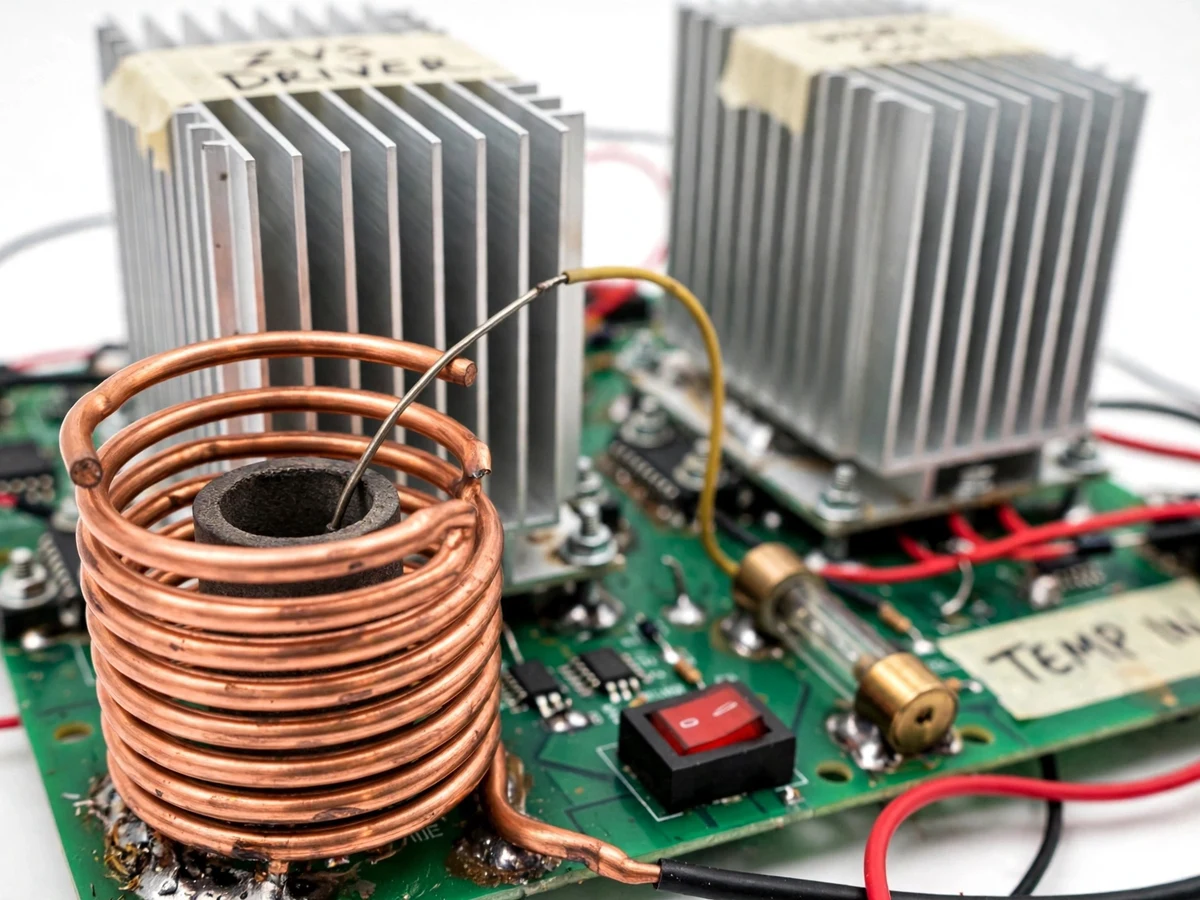
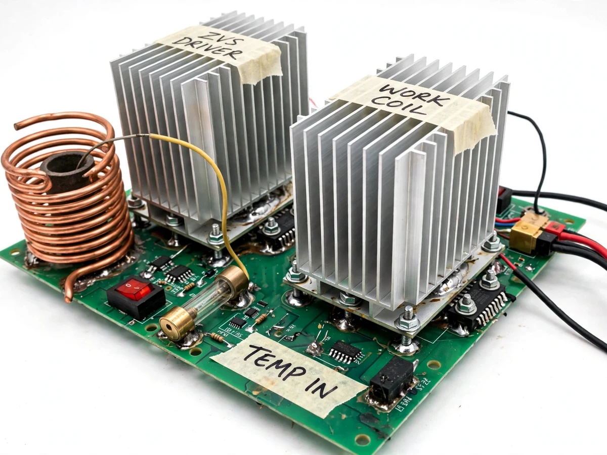
Electromagnetic induction is the cleanest way to heat metal without contact: an alternating current in a work coil induces eddy currents in anything conductive inside it, and the workpiece heats itself. Industrial induction furnaces exploit this at kilowatts; the student-scale version uses a ZVS (zero-voltage-switching) Mazzilli resonant driver — a self-oscillating LC tank that switches its MOSFETs when the voltage across them is near zero, so hundreds of watts can circulate with modest switching loss and a simple parts count. This project builds that as a working mini furnace: a heatsinked MOSFET driver board powers a hand-wound copper work coil, a graphite crucible sits inside the coil holding small metal charges such as solder or aluminium, and a K-type thermocouple feeds temperature back to a controller that backs off or cuts the drive at the configured over-temperature limit. The mains-derived DC supply is fused and switch-isolated, and a red panel toggle gives a hard manual stop. The result is a bench-scale demonstration of resonance, power magnetics, thermal design and control loops in one build.
230 V AC stepped down, rectified and filtered to a 12-48 V DC bus with dual fusing.
Follow the working sequence
How it works
- Mains 230 V AC is stepped down by a transformer, rectified and filtered to a DC bus of 12–48 V DC (design target), passing through mains-side and bus fuses and the red panel toggle switch.
- The ZVS driver — two MOSFETs cross-coupled around an LC tank formed by the work coil and the tank capacitors — self-oscillates, switching each MOSFET near zero volts so switching loss stays low.
- The resonant tank circulates a high-frequency current (tens of kHz, design target, set by coil inductance and tank capacitance) through the hand-wound copper work coil.
- The alternating magnetic field induces eddy currents in the graphite crucible and the metal charge inside it; their resistance converts the current into heat directly inside the material, while the copper coil itself stays cool.
- The K-type thermocouple tracks the crucible-zone temperature; the controller compares it with the setpoint and backs the drive down as the over-temperature limit is approached.
- At the over-temperature limit the drive is cut completely, and the panel switch stays available as a hard manual stop; the system re-arms only through a controlled reset, never automatically.
- Small charges (solder-class metals readily; small aluminium charges within the design envelope) complete the melt cycle, followed by a controlled cool-down with the optional fan position active if fitted. Actual melt times are recorded on the student's build per the test procedure — no time is claimed in advance.
Tech stack:
- ZVS / Mazzilli self-oscillating resonant driver topology
- Power MOSFETs (IRFP260N-class, typical) on finned heatsinks
- Hand-wound copper work coil + graphite crucible
- K-type thermocouple (typical) + temperature controller with over-temperature cutoff
- Mains transformer + rectifier + filter + dual fusing
- PCB, panel toggle switch, tank capacitors, wiring hardware
- Bench verification: multimeter, clamp meter, thermocouple meter
| Parameter | Value |
|---|---|
| Driver topology | ZVS Mazzilli self-oscillating resonant driver |
| Power MOSFETs | IRFP260N-class (typical part, not guaranteed) |
| DC bus voltage | 12–48 V DC (design target) |
| Input power | Approximately 100–300 W (design target) |
| Resonant frequency | Tens of kHz (design target, coil-dependent) |
| Work coil | 5–10 turns of copper tube (typical) |
| Crucible | Graphite, small-charge class (design target) |
| Melt targets | Solder-class metals; small aluminium charges (design target application) |
| Temperature sensing | K-type thermocouple (typical) |
| Over-temperature action | Drive cut at configured setpoint (implemented) |
| Supply protection | Mains fuse + DC bus fuse + panel toggle (implemented) |
| Cooling | Finned heatsinks on MOSFETs; fan position optional |
Project features
- [ZVS resonant driver board] The heart of the furnace: a self-oscillating Mazzilli driver using IRFP260N-class power MOSFETs (typical part, not guaranteed) on finned heatsinks, running from a 12–48 V DC bus (design target) and circulating a design-target 100–300 W of resonant power.
- [Hand-wound copper work coil] A typical 5–10 turns of copper tube wound around a former, tuned with the tank capacitors to resonate in the tens-of-kHz band (design target, coil-dependent) for strong coupling into the charge.
- [Graphite crucible for small melts] A graphite crucible sits inside the coil; solder melts readily and small aluminium charges reach melt temperature within the design power envelope (design target — per-metal charge sizes are specified in the test procedure).
- [Temperature control with over-temperature cutoff] A K-type thermocouple (typical) monitors the crucible zone; the controller reduces drive or cuts it entirely when the configured temperature limit is reached, and re-arms only on a controlled reset.
- [Fused, mains-derived DC supply] Mains power is stepped down, rectified and filtered to the DC bus, with fuse protection on both the mains side and the DC bus plus a hard panel toggle switch (implemented).
- [Thermal design] MOSFETs are heatsinked with an optional fan position; the layout keeps the high-current tank loop short and the tank capacitors close to the coil terminals (implemented cooling provision; fan optional).
- [Optional: temperature display] A seven-segment or LCD readout of the thermocouple temperature can be added on request (optional, not in the base build).
- [Future scope: closed-loop PID and logging] Temperature-profile PID control and serial data logging of the melt cycle are future-scope extensions, documented in the report and not part of the base build.
What is included
- ZVS driver board (assembled, heatsinked MOSFETs, hand-soldered prototype standard)
- Hand-wound copper work coil and graphite crucible
- K-type thermocouple with temperature controller and over-temperature cutoff wiring
- Fused mains-derived DC power supply with red panel toggle switch
- Bench test procedure: power-up sequence, melt test and temperature-cutoff verification steps
- Project report PDF (resonance theory, ZVS driver design, magnetics, thermal design, safety)
- PPT presentation for final review
- Viva Q&A preparation document (ZVS operation, resonance, eddy-current heating, safety)
Advantages
- ZVS (Mazzilli) self-oscillating resonant driver: two IRFP260N-class MOSFETs on finned heatsinks switch near zero volts, so hundreds of watts circulate in the LC tank at tens of kHz with modest switching loss and a simple parts count.
- Hand-wound copper work coil (typically 5–10 turns) tuned with tank capacitors for strong coupling; the alternating field induces eddy currents that heat the graphite crucible and charge directly while the coil itself stays cool.
- Real melts on the bench: a graphite crucible inside the coil melts solder-class metals readily and reaches aluminium melt temperature for small charges within the 100–300 W design envelope.
- Temperature-guarded build: a K-type thermocouple watches the crucible zone, the controller backs off the drive approaching the setpoint and cuts it at the over-temperature limit — re-arming only on a controlled reset — with a fused mains-derived DC supply, hard panel toggle switch and heatsinked MOSFETs.
Disadvantages
- The crucible and the charge stay dangerously hot long after switch-off — heat-resistant handling and adult supervision are mandatory for every powered run, and the driver must never run without heatsinks fitted.
- MOSFET thermal runaway is possible if cooling is compromised, and the driver draws high DC currents at full power — wiring must be sized as specified, never substituted with thinner leads.
- The oscillator radiates RF energy in the tens-of-kHz band — keep sensitive bench electronics and radios at a distance — and this is not a continuous-duty industrial furnace: run times and cool-down intervals are limited per the test procedure.
- All power, frequency and melt figures are design targets until the buyer's own build is tested and recorded; graphite crucibles oxidize and wear with repeated melts and are a consumable item.
Limitations & prerequisites
- Nothing is physically built before your order — all power, frequency and melt figures are design targets, honestly labeled; the per-order test procedure records what your build actually does.
- The crucible and the charge stay dangerously hot long after switch-off — heat-resistant handling and adult supervision are mandatory during every powered run.
- MOSFET thermal runaway is possible if cooling is compromised — never operate the driver without the heatsinks fitted, and respect the duty guidance in the test procedure.
- The driver draws high DC currents at full power — wiring must be sized as specified; never substitute thinner leads.
- The oscillator radiates RF energy in the tens-of-kHz band — keep sensitive bench electronics and radios at a distance while it runs.
- Not a continuous-duty industrial furnace — run times and cool-down intervals are limited per the test procedure.
- Graphite crucibles are consumable — they oxidize and wear with repeated melts; spares are a consumable item.
Frequently Asked Questions
Why does the ZVS driver stay efficient while circulating so much power?
Because it switches each MOSFET when the voltage across it is near zero (zero-voltage switching), so switching losses stay small even though the tank circulates far more current than the DC bus supplies. The resonant tank does the heavy lifting; the MOSFETs only top up the losses.
What can it actually melt?
Solder-class metals melt readily; the design-target envelope covers small aluminium charges (melting point 660 °C) at the rated input power. Per-metal charge sizes are specified in the test procedure, and anything larger is outside the design envelope.
How does the temperature control protect the build?
A K-type thermocouple watches the crucible zone. As the reading approaches the configured setpoint the controller backs the drive down, and at the over-temperature limit it cuts the drive completely; re-arming needs a controlled reset, never an automatic restart.
Is it safe to demonstrate in a college lab?
Only with the safety rules in the test procedure followed exactly: fused supply, no operation without heatsinks fitted, heat-resistant handling of the crucible, RF separation from other bench equipment, and adult supervision for every powered run. It is a power-electronics build, not a desk toy.
Is this project suitable for a final-year project?
Yes — for Electrical, Electronics and allied branches. It demonstrates resonant power conversion, magnetics, thermal design and closed-loop protection in one build, with honestly labeled design targets and a viva kit that explains the theory behind each stage. Suitable for B.E./B.Tech final-year projects in Electrical, Electronics and Power Electronics.
Components & software requirements
- ZVS / Mazzilli self-oscillating resonant driver topology
- Power MOSFETs (IRFP260N-class, typical) on finned heatsinks
- Hand-wound copper work coil + graphite crucible
- K-type thermocouple (typical) + temperature controller with over-temperature cutoff
- Mains transformer + rectifier + filter + dual fusing
- PCB, panel toggle switch, tank capacitors, wiring hardware
- Bench verification: multimeter, clamp meter, thermocouple meter
Delivery information
Built-to-order project. Delivery timeline is shared after order confirmation based on current queue.
Support terms
Complete documentation, setup guide, and viva preparation included. Support for setup and explanation provided.
Download free synopsis (PDF)
Enter your name and email — the synopsis PDF downloads immediately. We may send occasional project updates; no spam, unsubscribe anytime.