
More project photos (3)
The problem
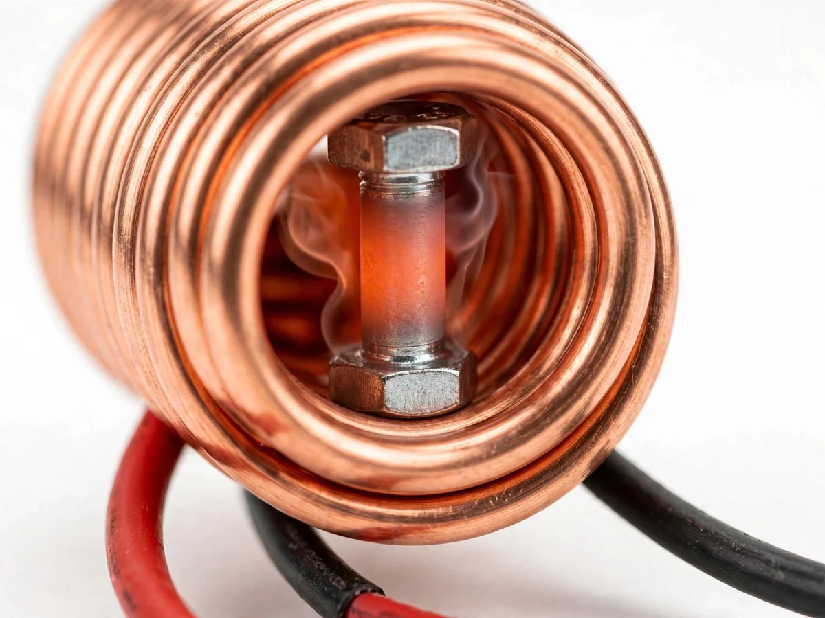
An induction heater melts the mystery out of electromagnetic heating: an alternating magnetic field induces eddy currents in a metal part placed inside a coil, and the part heats itself from the inside out — no flame, no contact, no heating element. Commercial units are sealed boxes that hide the power electronics. This project builds the classic DIY version from first principles: a ZVS (zero-voltage-switching) Royer oscillator driver board that automatically resonates a hand-wound copper work coil with its tank capacitors, powered by an ordinary 12-24 V DC supply. Students wind the coil themselves, assemble the MOSFET driver stage, tune the tank circuit, and watch a steel bolt glow red-hot inside the coil — a demonstration that makes resonance, skin effect and soft switching tangible in a way no simulation can. The build also teaches serious high-current practice: thick wiring, heatsinking, fast diodes and a disciplined safety procedure around hot metal, strong magnetic fields and high DC currents.
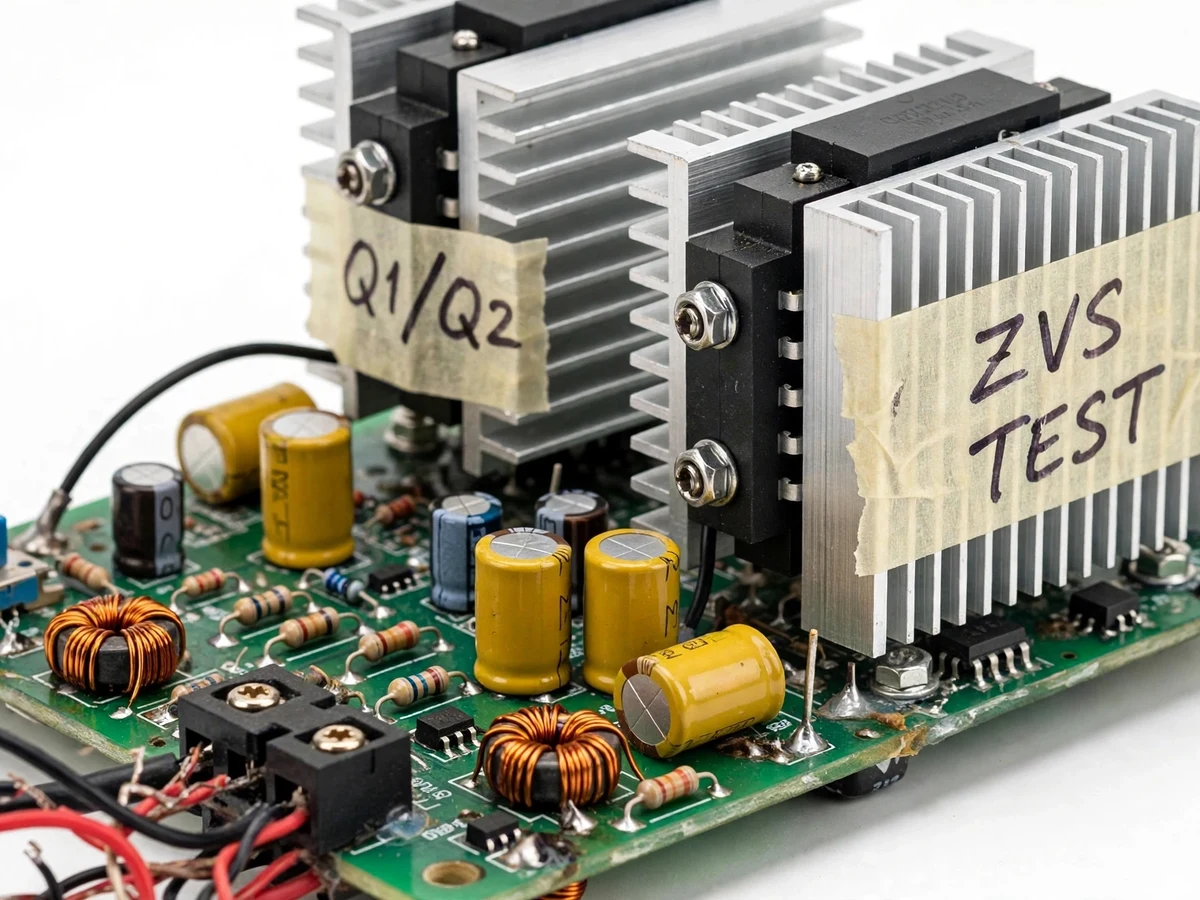
12-24 V DC high-current supply feeding the ZVS board through ferrite choke inductors.
Follow the working sequence
How it works
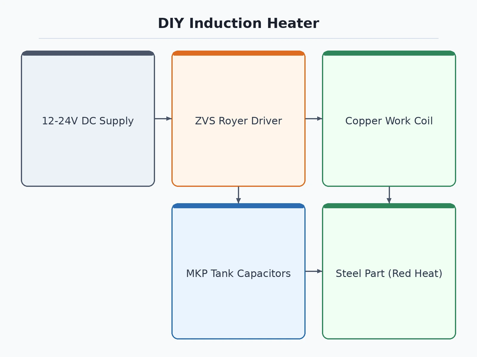
- The 12-24 V DC supply feeds the ZVS driver board through two ferrite choke inductors that keep the high-frequency switching current out of the supply.
- The two MOSFETs, cross-coupled through fast diodes and gate resistors, alternately switch so the LC tank (work coil + MKP capacitors) rings at its resonant frequency — each MOSFET always switches at near-zero voltage, which keeps switching losses low.
- The resonant current circulating in the copper work coil (many times the DC input current, design range) generates an intense alternating magnetic field inside the coil bore.
- A steel or iron part placed inside the coil experiences rapidly alternating flux; eddy currents and magnetic hysteresis heat the part from within, concentrated near the surface by the skin effect.
- Within tens of seconds (approximate demonstration target for an M8 bolt at 24 V input) the part reaches a visible red heat — the student removes DC power, lets the part cool on a fire-safe surface, and records input voltage, current and heating time.
- The student verifies resonance by observing the tank waveform, confirms the MOSFETs stay within safe temperature with the heatsinks and fan, and documents the full procedure with readings for the report.
Tech stack:
- ZVS Royer oscillator topology (self-resonant, soft switching)
- IRFP250 / IRFP260 N-channel MOSFETs
- MKP film capacitors (tank circuit)
- Hand-wound copper tube work coil
- 12-24 V DC high-current SMPS / bench supply
- Oscilloscope or frequency counter (tuning)
- Clamp meter (input current measurement)
Hardware requirements
- 2x IRFP250 (or IRFP260) N-channel MOSFETs with finned aluminium heatsinks and 12 V fan
- MKP film capacitors, 0.33 uF 1200 V class (design: 2 in parallel for the tank bank)
- Copper tube ~6 mm OD for the 8-turn work coil (design: ~45 mm coil inner diameter)
- 2x ferrite choke inductors, ~47-100 uH (design) for DC feed filtering
- UF4007 fast diodes and 470 ohm gate resistors for the driver stage
- 12-24 V DC supply rated for high continuous current (design up to 15-20 A)
- Perfboard / general-purpose PCB, thick hookup wire, ring terminals, enclosure standoffs
- M6-M10 steel bolts, nuts and short rods as heating demo parts
- Oscilloscope or frequency counter + DC clamp meter for tuning and measurement
| Parameter | Value |
|---|---|
| Driver topology | ZVS Royer (Mazzilli) self-oscillating, zero-voltage switching |
| Supply voltage | 12-24 V DC (design range) |
| DC input current | Up to 15-20 A (design range, supply-dependent) |
| Resonant frequency | Approximately 60-150 kHz (design range, coil/capacitor dependent) |
| Work coil | ~8 turns, ~6 mm OD copper tube, ~45 mm ID (design) |
| Tank capacitance | ~0.66 uF total, MKP film, 1200 V class (design) |
| MOSFETs | 2x IRFP250 / IRFP260 on heatsinks with fan cooling |
| Demo parts | M6-M10 steel/iron bolts, nuts, short rods |
| Heating result | Visible red heat on small steel parts (demonstration target, not a measured claim) |
| Heating time | Tens of seconds for an M8 bolt at 24 V (approximate demonstration target) |
Project features
- [ZVS Royer driver board] Two IRFP250 MOSFETs in a self-oscillating zero-voltage-switching Royer stage with gate resistors and UF4007 fast diodes — the standard DIY induction-heater topology, assembled on perfboard with full schematic.
- [Hand-wound copper work coil] Approximately 8 turns of 6 mm (design) copper tube wound to about 45 mm inner diameter, the actual heating element where the part sits.
- [Resonant tank circuit] MKP film tank capacitors (design 0.33 uF, 1200 V class) in parallel with the coil, resonating at an approximate 60-150 kHz design range — the student measures and tunes the real frequency.
- [Red-heat demonstration] Small steel and iron parts (M6-M10 bolts, nuts, short rods) heat to a visible red glow — the demonstration target of the build.
- [High-current DC supply] Runs from a 12-24 V DC supply rated for high current (design up to 15-20 A draw), with thick wiring and proper connectors throughout.
- [Thermal management] Both MOSFETs on finned aluminium heatsinks with a 12 V cooling fan — mandatory, because the driver stage runs hot under load.
- [Safety procedure] Written step-by-step safety protocol: pacemaker and metal-implant exclusion zone, no bare hands near the hot part, fire-safe work surface, and never running the coil without the tank capacitors connected.
- [Tuning and measurement guide] Procedures for checking resonance with an oscilloscope or frequency counter, measuring DC input current with a clamp meter, and documenting the heating demonstration for the report.
What is included
- Assembled and tested ZVS driver board (MOSFETs on heatsinks, tank capacitor bank, chokes)
- Hand-wound copper work coil, connected with thick high-current wiring
- 12-24 V DC supply guidance and wiring harness (supply rating matched to the build)
- Steel demo parts set (bolts, nuts, short rods)
- Circuit schematic and board layout diagram (PDF)
- Step-by-step build, tuning and measurement procedure
- Written safety protocol (magnetic-field exclusion, burn and fire precautions)
- Project report PDF (induction heating theory, ZVS operation, resonance, skin effect, measurements)
- PPT presentation for final review
- Viva Q&A preparation document (resonance, ZVS vs hard switching, eddy currents, skin effect, MOSFET thermal design)
Limitations & prerequisites
- Heats small ferromagnetic parts only — aluminium, copper and brass do not heat usefully in this design because their low resistivity and non-magnetic nature produce weak eddy-current heating.
- Maximum part size is limited by the ~45 mm (design) coil bore; larger parts will not couple well.
- Heating time and final temperature are approximate demonstration targets — they depend on the exact supply, coil and part, and no temperature figure is claimed as measured until the student's own build is tested.
- The driver MOSFETs run hot and the build must never operate without heatsinks and the cooling fan.
- Strong alternating magnetic field near the coil: keep pacemakers, metal implants, magnetic storage and watches well away during operation.
- This is an educational demonstration build, not an industrial heat-treatment unit — no claim is made about hardening, annealing quality or temperature uniformity.
Frequently Asked Questions
How does the heater actually heat the metal?
The ZVS driver makes the work coil ring at resonance, producing a strong alternating magnetic field. That field induces eddy currents in a steel part inside the coil, and the part's own electrical resistance turns those currents into heat — concentrated near the surface by the skin effect. No flame and no contact are involved.
What does ZVS mean and why does it matter?
Zero-voltage switching: each MOSFET turns on only when the voltage across it is near zero, because the circuit oscillates naturally at the tank's resonant frequency. This keeps switching losses and MOSFET heating far lower than hard-switched designs, which is why the simple Royer topology works at these power levels.
What metals can it heat?
Ferromagnetic metals — steel and iron parts like bolts, nuts and short rods. Aluminium, copper and brass heat very poorly in this design and are out of scope.
Is it safe for a student to build and demo?
Yes, with the written safety protocol followed strictly: high DC current wiring discipline, never touching the hot part, a fire-safe work surface, heatsinks and fan always fitted, and an exclusion zone for pacemakers, metal implants and magnetic media. The protocol is part of the deliverables.
What will I measure and tune myself?
The resonant frequency (oscilloscope or frequency counter), the DC input current (clamp meter), MOSFET/heatsink temperatures, and heating time for standard demo parts — all recorded in the report's measurement section.
Is this project suitable for a final-year project?
Yes — for Electrical and Electronics programs. It demonstrates power electronics (ZVS soft switching), magnetics (coil design), resonance, thermal design and disciplined high-current safety practice, with a dramatic working demo.
Components & software requirements
- ZVS Royer oscillator topology (self-resonant, soft switching)
- IRFP250 / IRFP260 N-channel MOSFETs
- MKP film capacitors (tank circuit)
- Hand-wound copper tube work coil
- 12-24 V DC high-current SMPS / bench supply
- Oscilloscope or frequency counter (tuning)
- Clamp meter (input current measurement)
Hardware requirements
- 2x IRFP250 (or IRFP260) N-channel MOSFETs with finned aluminium heatsinks and 12 V fan
- MKP film capacitors, 0.33 uF 1200 V class (design: 2 in parallel for the tank bank)
- Copper tube ~6 mm OD for the 8-turn work coil (design: ~45 mm coil inner diameter)
- 2x ferrite choke inductors, ~47-100 uH (design) for DC feed filtering
- UF4007 fast diodes and 470 ohm gate resistors for the driver stage
- 12-24 V DC supply rated for high continuous current (design up to 15-20 A)
- Perfboard / general-purpose PCB, thick hookup wire, ring terminals, enclosure standoffs
- M6-M10 steel bolts, nuts and short rods as heating demo parts
- Oscilloscope or frequency counter + DC clamp meter for tuning and measurement
Delivery information
Built-to-order project. Delivery timeline is shared after order confirmation based on current queue.
Support terms
Complete documentation, setup guide, and viva preparation included. Support for setup and explanation provided.
Download free synopsis (PDF)
Enter your name and email — the synopsis PDF downloads immediately. We may send occasional project updates; no spam, unsubscribe anytime.